Compact packet switching node storage architecture employing double data rate synchronous dynamic RAM

a packet switching node and storage architecture technology, applied in data switching networks, digital transmission, electrical equipment, etc., can solve the problems of data accumulation, high differential cost of fabricating two different switching nodes, instead of one, and temporary congestion conditions

Active Publication Date: 2005-09-29
IKANOS COMMUNICATIONS
View PDF11 Cites 17 Cited by
  • Summary
  • Abstract
  • Description
  • Claims
  • Application Information

AI Technical Summary

Benefits of technology

[0035] In accordance with a further aspect of the invention, in sequencing the plurality of memory burst unit memory read operations, the method further includes delaying scheduling of read burst units corresponding to packets destined to a congested output port.
[00

Problems solved by technology

By contrast, for access switching network nodes which aggregate uplink traffic and deaggregate downlink traffic, the speed mismatch between access ports (typically 100 Mbps or less) and the uplink ports (1 Gbps or more) often creates temporary congestion conditions at, and data accumulation in, the access switching nodes, requiring switching architecture designs supporting much larger memory stores to prevent packet drops.
The differential cost of fabricating two different switching nodes, instead of one, is high—currently estimated at an add

Method used


Image

  • Compact packet switching node storage architecture employing double data rate synchronous dynamic RAM
  • Compact packet switching node storage architecture employing double data rate synchronous dynamic RAM
  • Compact packet switching node storage architecture employing double data rate synchronous dynamic RAM

Examples


Embodiment Construction

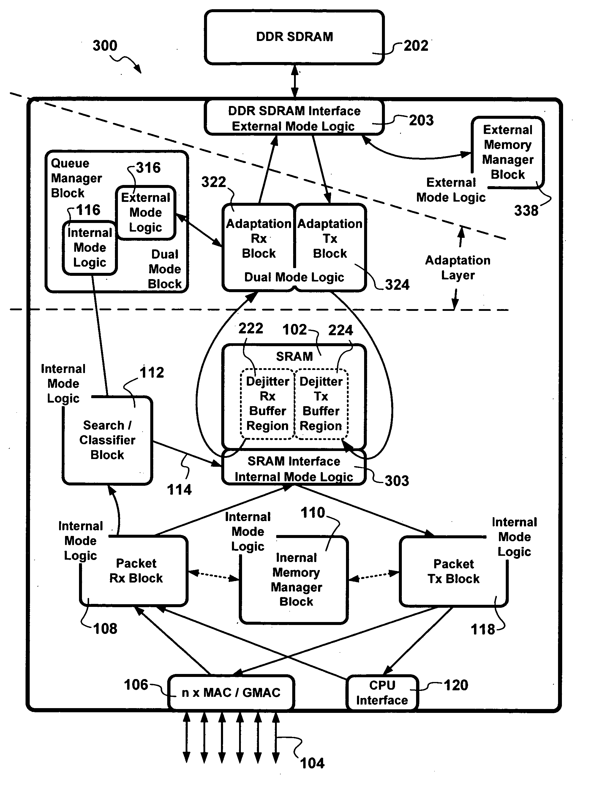
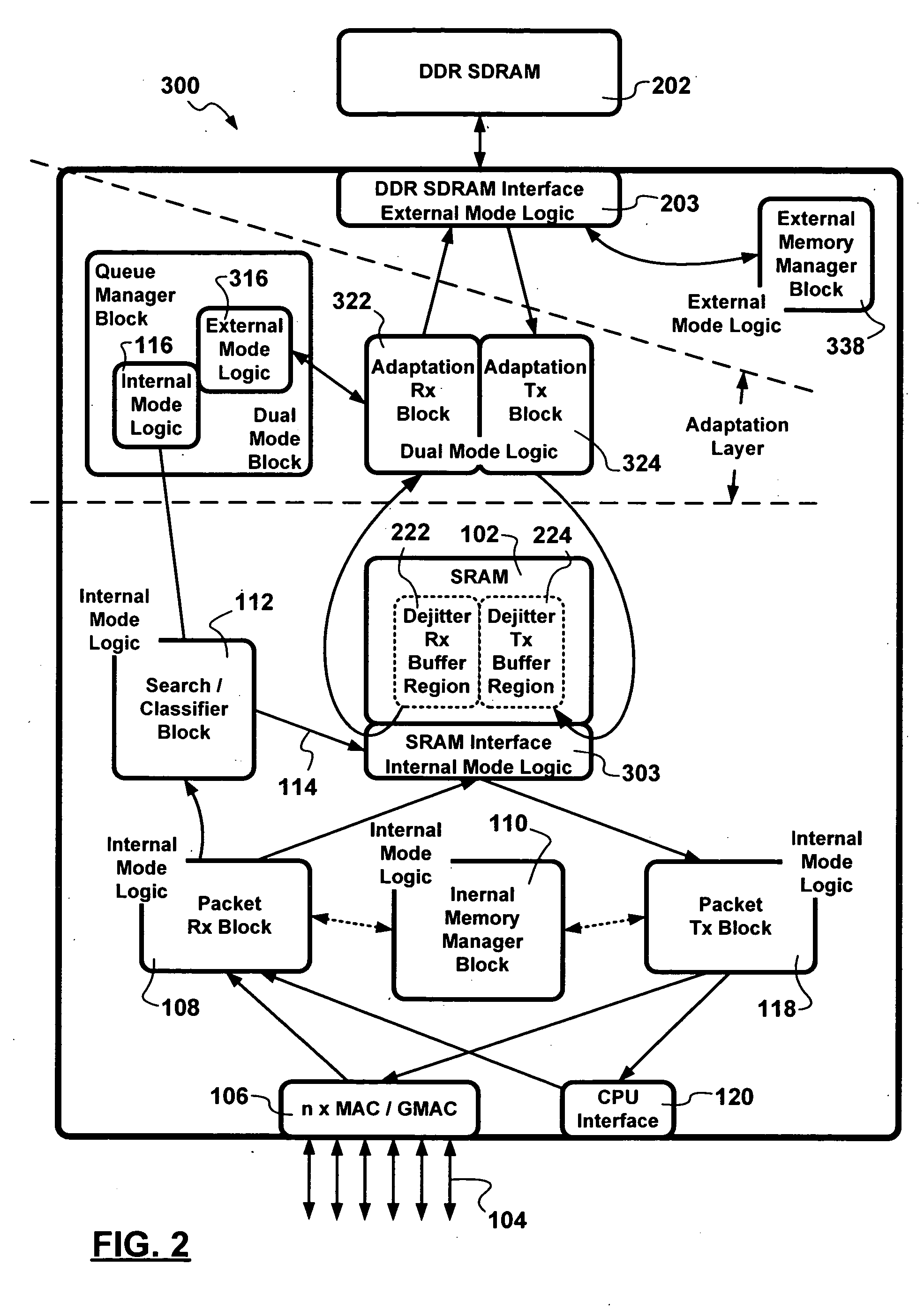
[0045] In accordance with a preferred embodiment, a two-chip / single-die switch architecture supporting both a small, embedded, packet storage memory such as, but not limited to, Synchronous Static Random Access Memory (SSRAM), and a large, externally attached, packet storage memory using Double Data Rate Synchronous Dynamic RAM (DDR SDRAM) is provided with minimal dual-mode logic manufactured on the same-die.

[0046]FIG. 2 is a schematic diagram showing elements implementing, in accordance with an exemplary embodiment of the invention, a two-chips / single-die switch architecture 300 with a large external DDR DSRAM memory storage 202.

[0047] In accordance with the exemplary embodiment of the invention, the packet data flow for the packet switch 300 employs blocks 102, 106, 108, 110, 112, 118, and 120 which operate in the single internal memory mode only as described above as if only the internal memory block 102 was employed, whether or not the ultimate location for packet data storage...


PUM


Abstract

A two-chip/single-die switch architecture and a method for accessing a DDR SDRAM memory store in a switching environment are presented. The two-chip/single-die architecture includes an internal memory storage block on the single-die, an external memory storage interface to a Double Data Rate Synchronous Dynamic Random Access Memory (DDR SDRAM), an external memory manager, and a packet data transfer engine effecting packet data transfers between an internal memory store and the external DDR SDRAM memory. The packet data transfer engine operates as an adaptation layer addressing issues related to employing appropriate: addressing schemes, granule sizes, memory transfer burst sizes, access timing, etc. The packet data transfer engine includes a minimal number of dual mode operational blocks such as: a queue manager, and adaptation receive and transmit blocks. The method relates to a packet data transfer discipline addressing random memory access latencies incurred in employing DDR SDRAM, using predictive bank switching to hide random access latencies, packet length dependent variable memory write burst lengths to minimize bank switching, and performing memory read and write operations during corresponding read and write windows. Advantages are derived from the a space-efficient two-chip/single-die switching node architecture implemented with a reduced amount of dual mode logic, and also from DDR SDRAM bandwidth utilization efficiencies.

Description

FIELD OF THE INVENTION [0001] The invention relates to storage of packets at a packet switching node, and in particular to methods and apparatus for storing packets at a single-chip packet switching node. BACKGROUND OF THE INVENTION [0002] In the field of packet-switched communications, switching communications network nodes employ a store-and-forward discipline in processing packets conveyed. Storing packets at the switching network node is performed in accordance with a packet storage discipline and requires memory data storage. [0003] The amount of storage memory required to store packets at a switching node is related to the network environment in which the switching node is employed. [0004] For a switching node employed in a Local Area Network (LAN), typically the total bandwidth available to convey packets in and out of the switching node far exceeds the switching capacity of the switching node, therefore only a small amount of memory storage is required to store packets pendi...

Claims


Application Information

Patent Timeline
IPC IPC(8): H04L12/56H04L12/28
CPCH04L49/103H04L49/90H04L49/352H04L49/109H04L49/9023
Inventor BARRACK, CRAIGWANG, YEONGCHANG, RONG-FENG
Owner IKANOS COMMUNICATIONS
Why Eureka
Try Eureka