
System using a signaling protocol for controlling voice calls originating in a circuit switching telephone network and routed over a packet switching network

a packet switching and voice call technology, applied in the field of packet switching networking systems, can solve the problems of incompatibility of newer packet switching network protocols, inability to handle the protocols of the newer packet switching network, and high cost of long-distance telephone services carried over the pstn

Inactive Publication Date: 2008-05-06
CISCO TECH INC
View PDF66 Cites 16 Cited by
  • Summary
  • Abstract
  • Description
  • Claims
  • Application Information

AI Technical Summary

Benefits of technology

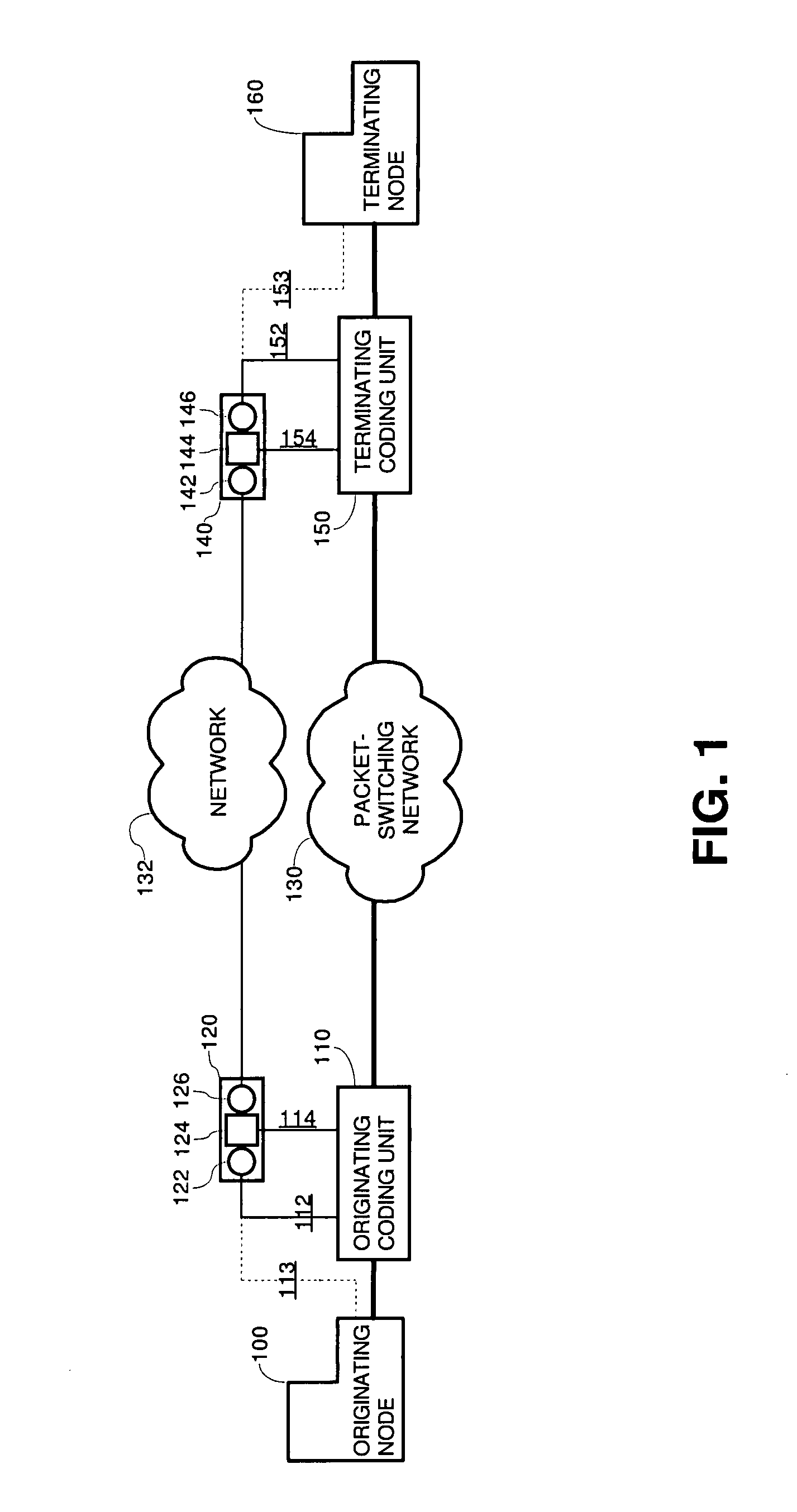
[0008]In particular, the common signaling protocol specifies that messages include a network-wide call identifier that allows a voice call to be uniquely identified throughout the network. Accordingly, signaling units that employ this common signaling protocol can be provided within the network for handling signaling interworking and protocol conversion (if necessary) of the legacy systems. The voice data is handled by coding units. The call identifier in the common signaling protocol enables the voice signaling to be extracted from the voice call, processed separately from the voice call, and rejoined at the terminating site, in a network having a number of different logical and physical implementations of virtual switching sites. Thus, a flexible solution for integrating with legacy systems is attained because voice signaling processing is separated from voice data handling.

Problems solved by technology

Long-distance telephone services carried over the PSTN are expensive.
These legacy systems, however, do not handle the protocols for the newer packet-switching networks, and, the newer packet-switching network protocols in common use are incompatible with one another.

Method used


Image

  • System using a signaling protocol for controlling voice calls originating in a circuit switching telephone network and routed over a packet switching network
  • System using a signaling protocol for controlling voice calls originating in a circuit switching telephone network and routed over a packet switching network
  • System using a signaling protocol for controlling voice calls originating in a circuit switching telephone network and routed over a packet switching network

Examples


Embodiment Construction

[0007]These needs, and other needs that will become apparent from the following description, are addressed by the present invention, which implements a common signaling protocol that unifies protocols for various legacy and newer systems for communicating voice calls transparently over a packet-switched network. As used herein, a “voice call” refers to both the signaling information necessary to establish and tear down a voice connection (i.e., a communication link satisfying bandwidth, latency, and quality of service requirements for near toll quality voice communication) and the voice data borne over the voice connection. Voice data includes human voice as well as data embedded in a voice signal, such as modem data, and facsimile data. The voice signaling, associated with the voice data, can be embedded in the same channel as the voice data, time-division multiplexed with the voice data on the same physical line or channel, or present on a separate channel from the voice data.

[000...


PUM


Abstract

Communicating voice over a packet-switching network is implemented on a telecommunications network that includes the packet-switching network, two coding units coupled to the packet-switching network and two signaling apparatuses. Signaling data for establishing the voice call is received by an originating signaling apparatus, which generates a message that encapsulates the signaling data in accordance with a common signaling protocol, and transmits the message to a destination signaling apparatus. The message, in accordance with the common signaling protocol, includes a call identifier that uniquely identifies the voice within the packet-switching network, the network address of a signaling apparatus, and / or a connection descriptor for a coding unit.

Description

CROSS-REFERENCE TO RELATED APPLICATIONS[0001]This is a continuation of and claims the benefit of priority under 35 U.S.C. §120 to U.S. application Ser. No. 09 / 343,090 entitled “Signaling Protocol for Controlling Voice Calls in a Packet Switching Network”, filed Jun. 30, 1999 now U.S. Pat. No. 6,658,022; which is a continuation-in-part of U.S. application Ser. No. 09 / 163,312 entitled “Communicating Voice over a Packet-Switching Network”, filed on Sep. 30, 1998 and issued as U.S. Pat. No. 6,570,869; all of which are incorporated by reference in their entirety for all purposes as if fully set forth herein.FIELD OF THE INVENTION[0002]The present invention relates to telecommunications and more particularly to packet switched networking systems capable of carrying voice traffic.BACKGROUND OF THE INVENTION[0003]Recent legislative changes in the United States have promoted competition in the telecommunication industry and spurred demand for new services at lower prices. These trends are pr...

Claims


Application Information

Patent Timeline
IPC IPC(8): H04L12/50H04J3/16H04L12/64H04M7/00
CPCH04L12/6418H04M7/006H04M7/063
Inventor WEST, ANDREWSHRIVER, DOUGLAS C.REDNOR, FRED
Owner CISCO TECH INC
Learn More