Hand-held power tool with a suction device

Active Publication Date: 2006-05-23
HILTI AG
View PDF12 Cites 48 Cited by
  • Summary
  • Abstract
  • Description
  • Claims
  • Application Information

AI Technical Summary

Benefits of technology

[0014]The receiving chamber advantageously has a cylindrical, preferably sleeve-like shape, which permits to provide a large surface for separation of particles. If necessary, the surface can include a separating filter which forms a part of the surface. In addition, cleaning of a cylindrical rec

Problems solved by technology

During cutting, particles, e.g., dust, cause a significant contamination of the work environment.
In particular, during working in living spaces or in areas where food is stored or electronic means is stored or produced, contamination is undesirable

Method used


Image

  • Hand-held power tool with a suction device
  • Hand-held power tool with a suction device
  • Hand-held power tool with a suction device

Examples


Example

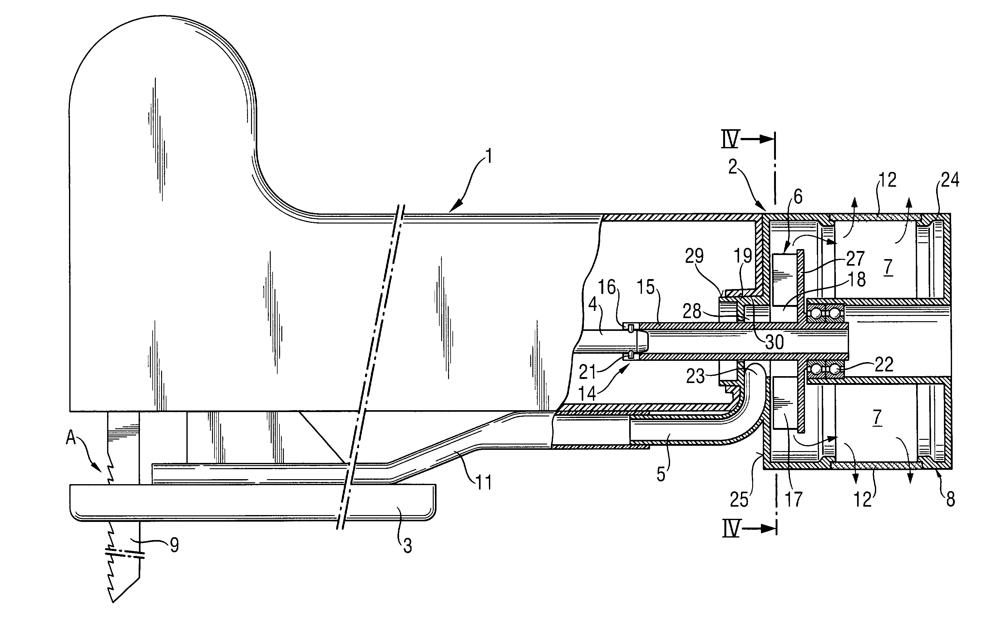
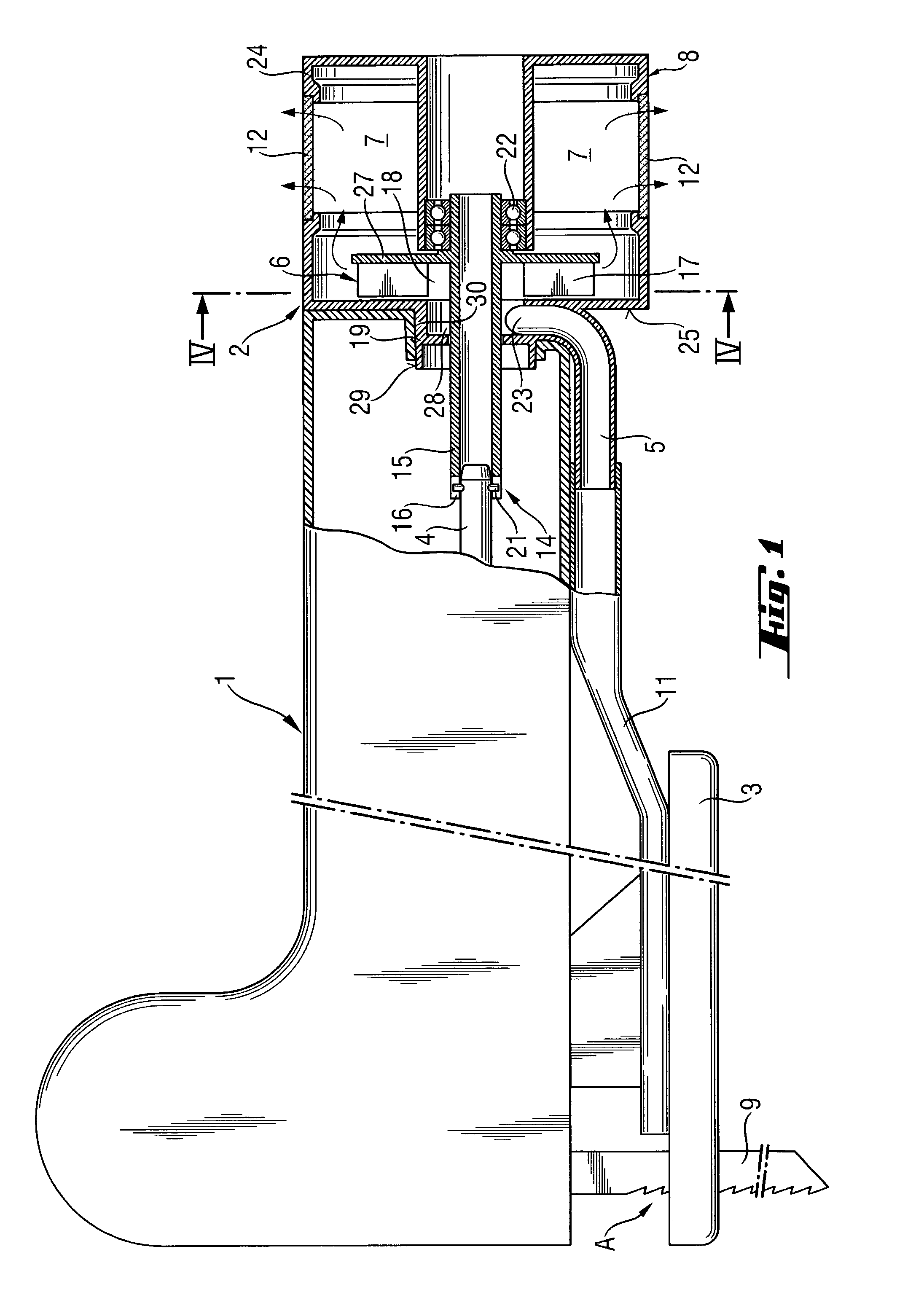
[0021]A hand-held power tool shown in FIGS. 1–4, which includes a suction device according to the present invention and which is formed, e.g., as a compass saw, has a motor-driven drive shaft 4 for a working tool 9 and includes a suction device 2 releasably connectable with the power tool housing 1 and formed as a separate modular unit. The power tool or compass saw has a support plate 3 connectable with the housing 1 for guiding the power tool along a working piece (not shown). Between the support plate 3 and the housing 1, there is provided a suction conduit 11 for removing separated, by the working tool 9, material, in particular dust, from a cutting region A of the working tool 9.

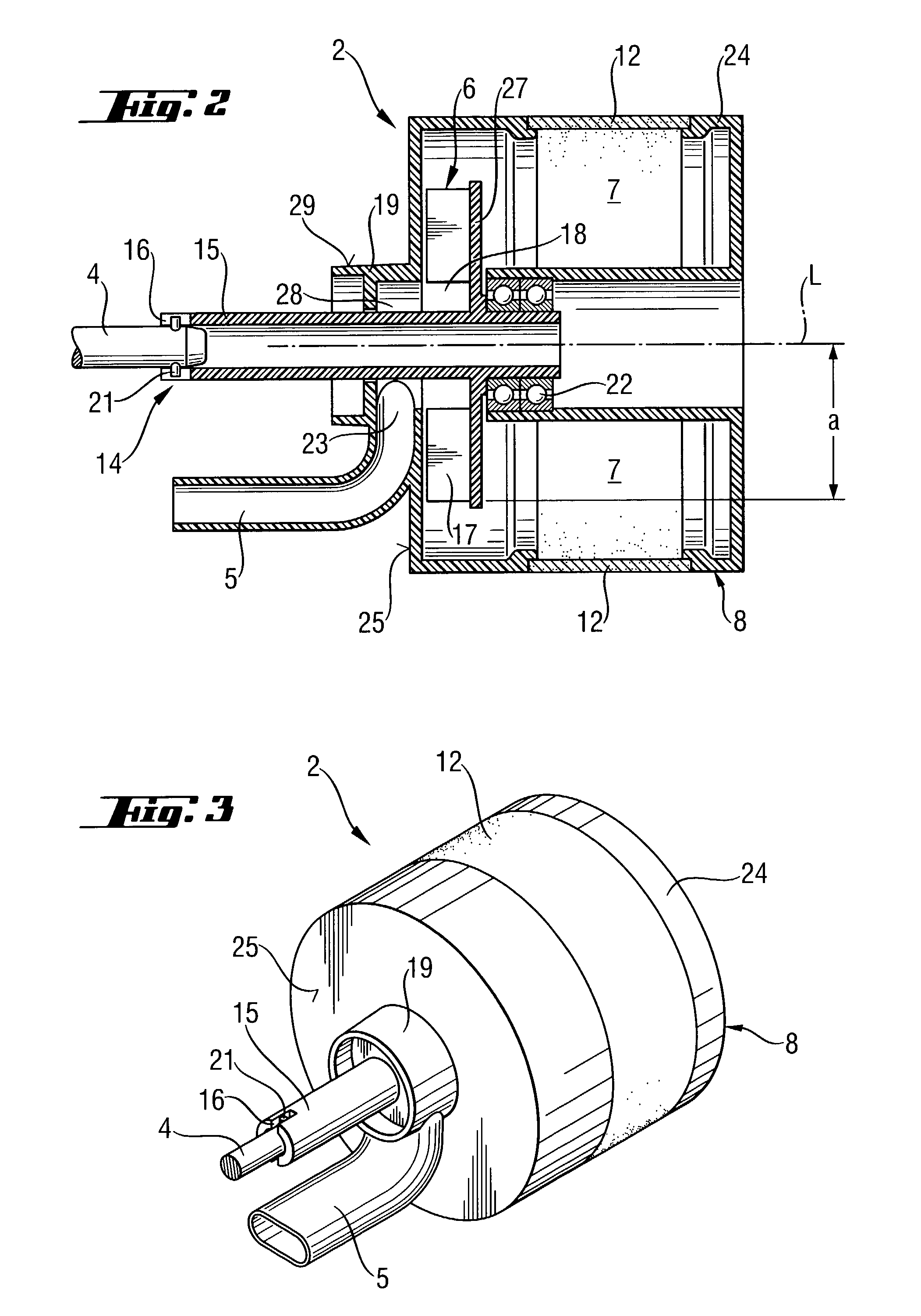
[0022]The suction device 2 has a suction conduit 5 connected with the suction conduit 11 and through which the removable material is conducted into the suction device 2. The suction conduit 5 has a feeding opening 23 arranged centrally with respect to an impeller 6. The suction device 2 further includes...


PUM

PropertyMeasurementUnit
Shapeaaaaaaaaaa
Precipitation enthalpyaaaaaaaaaa

Abstract

A hand-held power tool inclLldes motor-driven drive shaft (4) for driving a working tool (9) and located in the tool housing (1), and a suction device (2) formed as a modular unit releasably connectable wYith the tool housing (1) and having a suction conduit (5), a receiving chamber (7), a precipitation device (8) located in the receiving chamber (7), and an impeller (6) driven by the drive shaft (4) of the power tool and located between the suction conduit (5) and the precipitation device (8).

Description

BACKGROUND OF THE INVENTION[0001]1. Field of the Invention[0002]The present invention relates to a hand-held power tool having a housing, a motor-driven drive shaft for driving a working tool and located in the housing, and a suction device formed as a modular unit and releasably connectable with the power tool housing, with the suction device having a suction conduit, a receiving chamber, a precipitation device located in the receiving chamber, and an impeller driven by the drive shaft of the power tool.[0003]2. Description of the Prior Art[0004]Hand-held power tools of the type described above are used for cutting concrete, wood and the like. During cutting, particles, e.g., dust, cause a significant contamination of the work environment. In particular, during working in living spaces or in areas where food is stored or electronic means is stored or produced, contamination is undesirable and even not allowed. For this reason, the particles or dust should be removed. To this end, t...

Claims


Application Information

Patent Timeline
IPC IPC(8): B26B7/00B23B47/34B23D59/00B23Q11/00B25D17/18B25F5/00
CPCB23Q11/0046B23D59/006
Inventor MULLER, STEPHANBAXIVANELIS, KONSTANTINNEUMEIER, MICHAEL
Owner HILTI AG
Why Eureka
Try Eureka