Water jet cutting machine

a cutting machine and water jet technology, applied in the direction of metal-working machine components, manufacturing tools, saw chains, etc., can solve the problems of large operating space requirements, and large operating space requirements

Inactive Publication Date: 2006-05-23
ADKINS DANIEL +2
View PDF29 Cites 24 Cited by
  • Summary
  • Abstract
  • Description
  • Claims
  • Application Information

AI Technical Summary

Problems solved by technology

One difficulty that has been encountered using such a robotic arm carried water jet cutter results from the relatively large amount of operating space often required for placement and movement of the arm, especially when used for trimming edges or borders of a workpiece.
Such large operating space requirements can often severely limit and even, in some cases, prevent the simultaneous use of two or more robotic arm cutters to reduce border cutting time, as well as aperture cutting time where several holes and / or slots are to be cut in a single workpiece.
Such limitations arise due to the necessity of avoiding collisions between two or more simultaneously operating robotic arms.
Another difficulty that has been encountered using a robotic arm mounted water jet cutting tool is in the relatively large amount of time required to cut an individual hole in a workpiece.
Furthermore, if space requirements do not permit the ganging of two or more robotic arm cutters to simultaneously cut two or more holes required in a workpiece, then, typically, it can take at least 2.0 seconds for one robotic arm cutter to cut each separate hole sequentially.
Still another difficulty encountered in using a computer controlled robotic arm carried water jet cutting tool is the relatively high cost of each such arm.

Method used


Image

  • Water jet cutting machine
  • Water jet cutting machine
  • Water jet cutting machine

Examples


Embodiment Construction

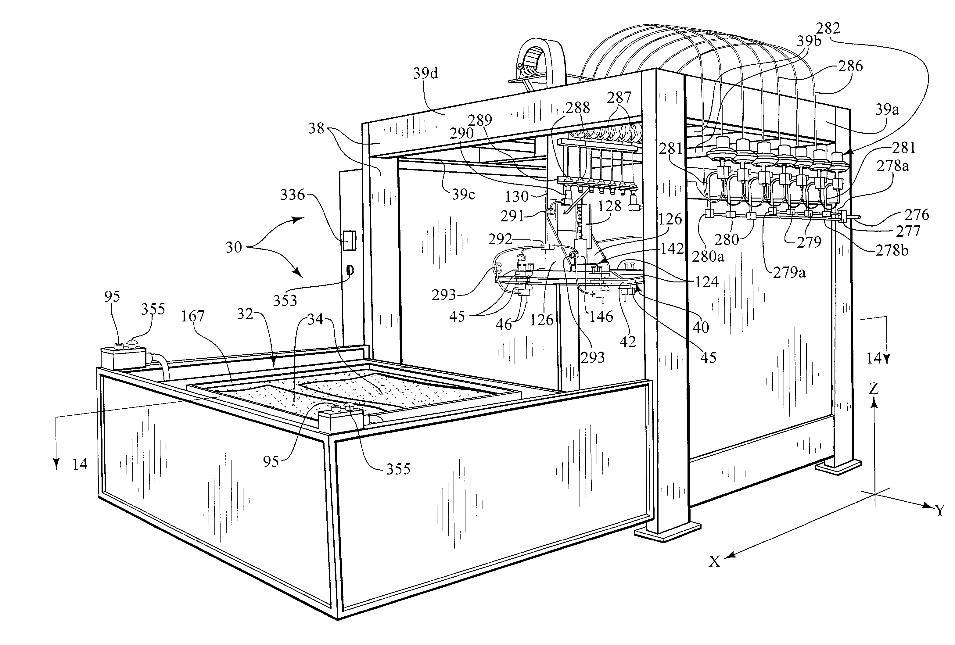
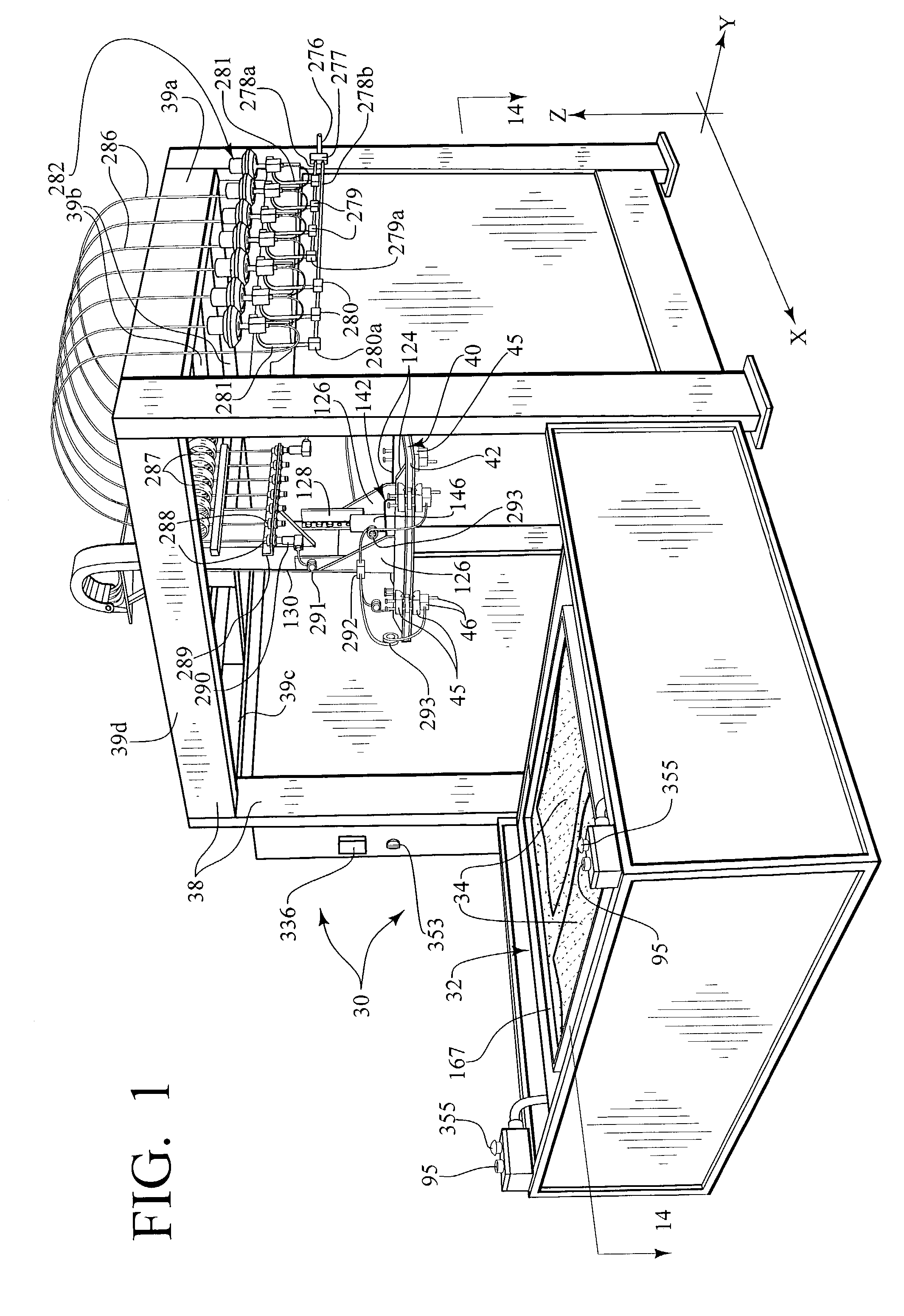
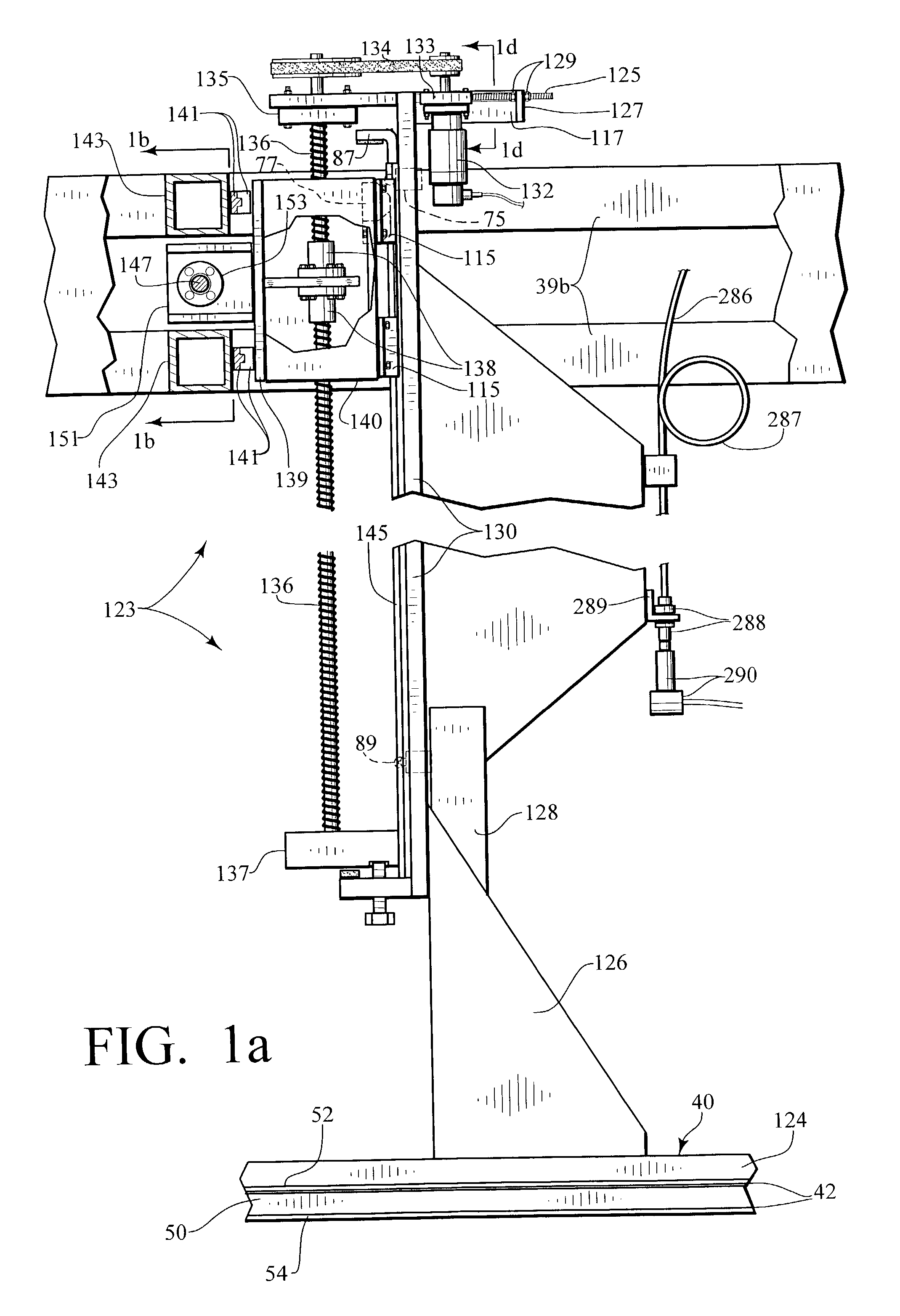
[0056]Referring now to the drawing figures and, in particular, to FIGS. 1–17, there is shown, in a preferred embodiment of my invention, a high pressure water jet cutting machine, an overall view of which is shown in FIG. 1 and generally designated 30. The machine 30 includes a table 32 for supporting one or more workpieces 34 to be cut. The table 32 is mounted on a set of conventional linear motion slide blocks and rails 36 (FIGS. 14–15) for movement between an operative position, within a box frame 38 having upper beam members 39a, b, c and d (FIG. 1) of the machine 30, and an extended, workpiece loading / unloading position in front of the frame, the table being in the latter mentioned position in FIGS. 1 and 14. The machine 30 also includes a cutting apparatus, generally designated 40 (FIGS. 1 and 6), which is located within the frame 38 over the table 32, when operatively positioned, which can be adapted for cutting both the borders of the workpieces 34 as well as openings, holes...


PUM

PropertyMeasurementUnit
widthaaaaaaaaaa
angleaaaaaaaaaa
angleaaaaaaaaaa

Abstract

A machine for cutting the border of a workpiece using one or more water jet cutting tools separately carried by one or more monorail track mounted carriage assemblies is disclosed. The machine can also include an aperture forming apparatus for forming circular openings and / or elongated slots in the workpiece prior to / or simultaneously with the border trimming operation, all while the workpiece occupies a single work station in the machine. In one embodiment, the aperture forming apparatus features a cutting tool mounted on an elongate arm affixed to and extending from a plate which is fixedly oriented in a horizontal plane. While so oriented, a motor and gear assembly causes the plate to wobble in a circular pattern in the plane to, in turn, cause the tool to make a circular cut in the workpiece. In another embodiment of the apparatus, a motor rotates a cam carried on a free end of a stationary arm, the cam containing an eccentrically mounted cutting tool.

Description

[0001]This application includes a CD-ROM appendix. The total number of compact discs in the appendix, including a duplicate, is two. The size of the file is 120 KB, saved under the file name of Proto_Type—4_HSRV_FINAL—10PART1—2.slc, created on Jul. 21, 2002.BACKGROUND OF THE INVENTION[0002]This invention relates generally to high pressure water jet cutting machines for both edging and bordering, and for forming circular openings and elongated slots in a workpiece. More specifically, the invention relates to such machines wherein bordering is accomplished by one or more water jet cutting tools separately carried on one or more monorail track mounted carriage assemblies and wherein aperture formation is accomplished by one or more cutting tools separately mounted on a like number of arms extending from a plate which is fixedly oriented in a horizontal plane, while circularly oscillating in such plane, or by one or more cutting tools eccentrically positioned on a like number of cams, w...

Claims


Application Information

Patent Timeline
Patent Type & Authority Patents(United States)
IPC IPC(8): B26D5/08B23Q1/01B26D3/10B26D7/00B26F3/00
CPCB23Q1/012B26F3/004B26D7/0006B26D3/10Y10T83/0591Y10T83/2066Y10T83/364Y10T83/8727Y10T83/8729Y10T83/873Y10T83/929
Inventor ADKINS, DANIEL
Owner ADKINS DANIEL
Why Eureka
Try Eureka