Head and a process for filling containers with powder material

a technology of powder material and filling method, which is applied in the direction of packaging goods, instruments, transportation and packaging, etc., can solve the problems of low volumetric filling method accuracy, inability to complete and correct fill, and the conventional filling method outlined above betrays a drawback

Inactive Publication Date: 2006-05-23
AZIONARIA CONSTR MASCH AUTOMATICHE A C M A SPA
View PDF7 Cites 14 Cited by
  • Summary
  • Abstract
  • Description
  • Claims
  • Application Information

AI Technical Summary

Benefits of technology

[0018]In particular, it is an object of the invention to provide a head and a process for filling containers with powder material such as will enable single containers to be filled with a precise quantity of well-compacted powder.

Problems solved by technology

The conventional filling method outlined above betrays a drawback however, in the case of machines handling powder material, deriving from the fact that the material does not settle properly inside the container.
It will be evident that during the course of the fill, and especially toward the final stages, a part of the material tends to remain outside the container and scatter into surrounding space, with the result that a complete and correct fill is rendered impossible.
Due to the low accuracy of volumetric filling methods, the measurement of the quantity of material introduced into the single container is notably lacking in precision and a correct fill is never achieved.
Nonetheless, this prior art solution likewise betrays a notable drawback deriving from the scant effectiveness of the movement induced in the container by the shaker device.

Method used


Image

  • Head and a process for filling containers with powder material
  • Head and a process for filling containers with powder material
  • Head and a process for filling containers with powder material

Examples


Embodiment Construction

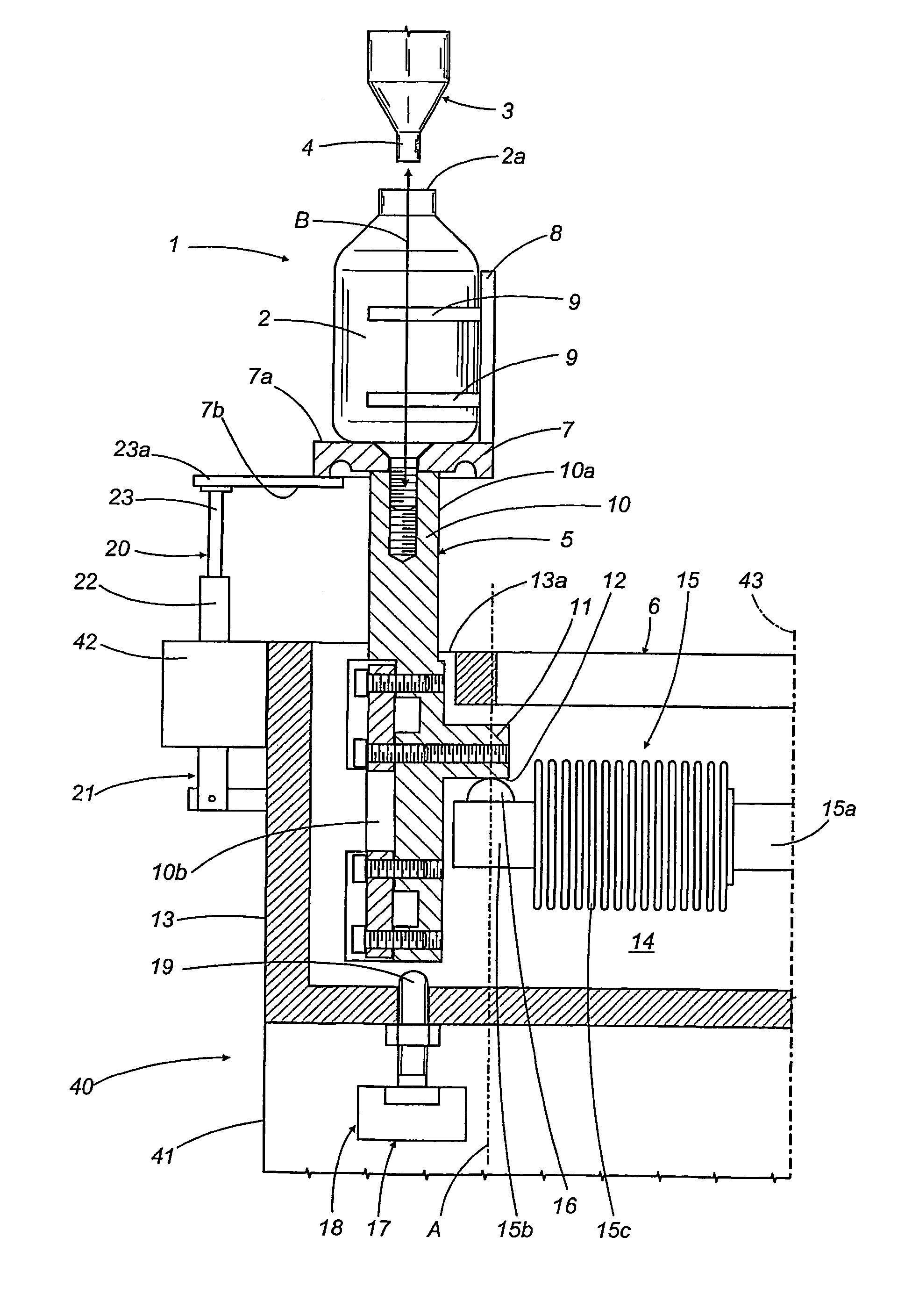
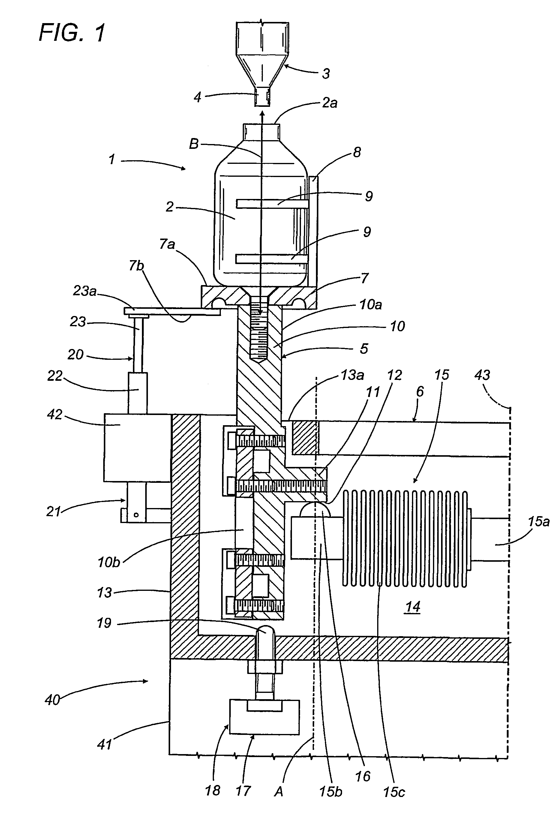
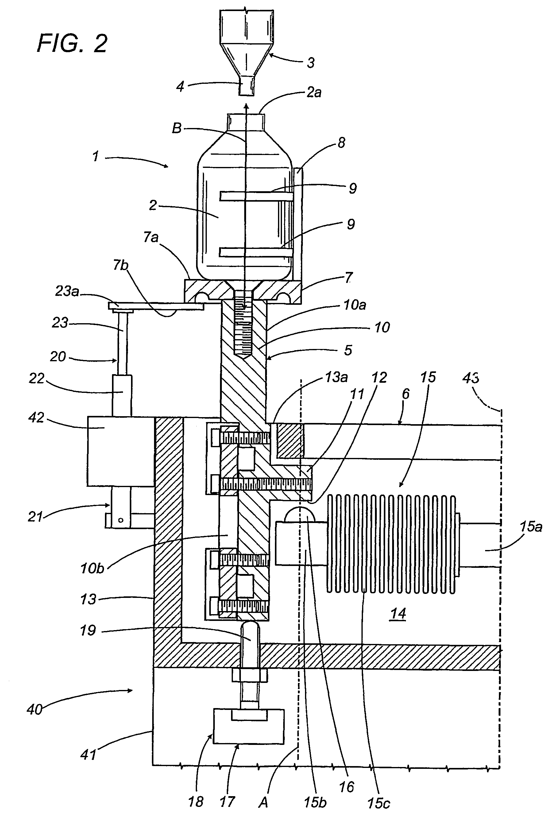
[0024]With reference to the drawings, 1 denotes a filler head, in its entirety, by which containers 2 each presenting a mouth 2a uppermost are filled with measured quantities of a powder material.

[0025]The head 1 forms part of a filling machine not illustrated in the drawings. Such a machine comprises a carousel 40 indicated only in part, presenting a base-plate 41 and a horizontal disc 42 rotatable about a vertical axis 43. The carousel 40 carries a plurality of filler heads 1 ordered circumferentially around the disc 42. As the carousel 40 rotates, the filler heads 1 are advanced along a circular filling path extending between an infeed station at which empty containers 2 are placed on the carousel 40, each aligned with a relative filler head 1, and an outfeed station at which filled containers 2 are removed from the carousel 40 and conveyed toward a unit by which a cap is applied to the mouth 2a.

[0026]Each filler head 1 comprises a dispensing element 3 of conventional embodiment...


PUM

PropertyMeasurementUnit
reciprocating movementaaaaaaaaaa
weightaaaaaaaaaa
cohesionaaaaaaaaaa

Abstract

A filler head (1) carried by the carousel of a rotary powder filling machine comprises a dispensing element (3) by which a predetermined quantity of powder material is directed into a container (2) positioned on a platform assembly (7, 5) carried by a hollow frame (13); the dispensing element (3) is interlocked to a dynamometer (15) housed in the cavity (14) of the frame (13) and controllable thus during the step of filling the container (2). The platform support (5) is associated with a first actuator (18) mounted at the bottom of the frame (13) and designed to separate the selfsame support (5) from the dynamometer (15), also with a second actuator (21) by which the container (2) is caused to shake in a direction (B) that causes the powder material to settle in the container (2) during the filling operation.

Description

[0001]This application is the national phase of international application PCT / IB02 / 00811 filed Mar. 18, 2002 which designated the U.S. and that international application was published under PCT Article 21(2) in English. This application claims priority to Italy Patent application number BO2001A 000156 filed Mar. 20, 2001.[0002]1. Technical Field[0003]The present invention relates to a head, and to a process, for filling containers with powder material.[0004]2. Background Art[0005]In particular, the present invention finds application advantageously in the art field of automatic filling machines equipped with a carousel carrying a plurality of filler heads by which liquid or powder material is batched into containers, each head equipped with a dispensing device designed to direct a given quantity of material by free fall into a relative container positioned on a platform assembly.[0006]The prior art embraces automatic machines for filling containers with liquid or powder material in ...

Claims


Application Information

Patent Timeline
Patent Type & Authority Patents(United States)
IPC IPC(8): B65B1/34
CPCB65B1/34G01G23/04G01G21/23G01G13/02
Inventor GHIZZI, STEFANOCAVALLARI, STEFANO
Owner AZIONARIA CONSTR MASCH AUTOMATICHE A C M A SPA
Why Eureka
Try Eureka