Surgical perforation device with curve

a perforation device and curve technology, applied in the field of creating perforations in materials, can solve the problems of significant forward momentum of needles used in this procedure, damage to vessel walls, and high rigidity of needles, and achieve the effect of reducing the risk of unintentional injury to other areas of the hear

Inactive Publication Date: 2006-05-23
BOSTON SCI MEDICAL DEVICE LTD
View PDF29 Cites 169 Cited by
  • Summary
  • Abstract
  • Description
  • Claims
  • Application Information

AI Technical Summary

Benefits of technology

[0007]The invention provides a surgical device for creating a perforation in material of a patient, including in particular, material that comprises the interatrial septum. The invention seeks to provide a device that is associated with a decreased risk of unintentional injury to other areas of the heart.
[0009]In accordance with a further aspect, the invention provides a device for creating a perforation in a heart septum. The device comprises an elongate member having a proximal region and a distal region capable of adopting a curved shape; and a functional tip at the distal region for delivering energy to create the perforation in the septum. When the functional tip advances through the septum, the distal region adopts a curved shape to direct the functional tip in a desired direction. The curved shape may be defined by a radial arc and the functional tip may be directed away from cardiac structures. In particular, the functional tip is directed away from cardiac structures in order to decrease the risk of unwanted injury.
[0015]Thus, the invention relates to a transseptal device configured for decreasing the likelihood of unintentional cardiac injury. The device may comprise a curve at the distal end of the device. The curved region at the distal end of the device is made of an elastic material such that the distal end of the device conforms to an internal lumen of a guiding catheter in order to be advanced through the guiding catheter within the vasculature. The distal end of the device remains inside the guiding catheter while the functional tip is exposed and then positioned against the desired perforation location on the septum. This ensures that the device remains straight while it is being positioned and during perforation. Once the device has perforated the septum, it is advanced out of the guiding catheter and through the perforation. This allows the distal end to take on its natural curve within the left atrium. As a result of the curve the functional tip does not continue to move forward towards the posterior wall of the heart. The functional tip is positioned at the end of the curve, and is unlikely to inadvertently injure other structures within the heart. If the operator inadvertently advances the device beyond the desired location, the curved portion of the device, instead of the functional tip, would contact the posterior wall of the heart. The curved portion is constructed of a material that is unlikely to cause any damage to heart structures.

Problems solved by technology

The needles used in this procedure are very stiff and can damage the vessel walls as they are being advanced.
Once the needle makes the perforation, the needle may have significant forward momentum, which can be difficult to control.
If too much force is applied there is the possibility of the needle perforating the septum and continuing to advance so far that damage is done to other areas of the heart.
However, even with this method there is danger of causing unwanted injury to other areas of the heart because the perforating device can be advanced too far unknowingly while RF current is being applied.
In particular, patients with a muscular septum, as well as those with a thick septum can benefit from an alternative to the transseptal needle puncture (Benson et al, 2002), as it is difficult to control the amount of mechanical force required to create the puncture.

Method used


Image

  • Surgical perforation device with curve
  • Surgical perforation device with curve
  • Surgical perforation device with curve

Examples


Embodiment Construction

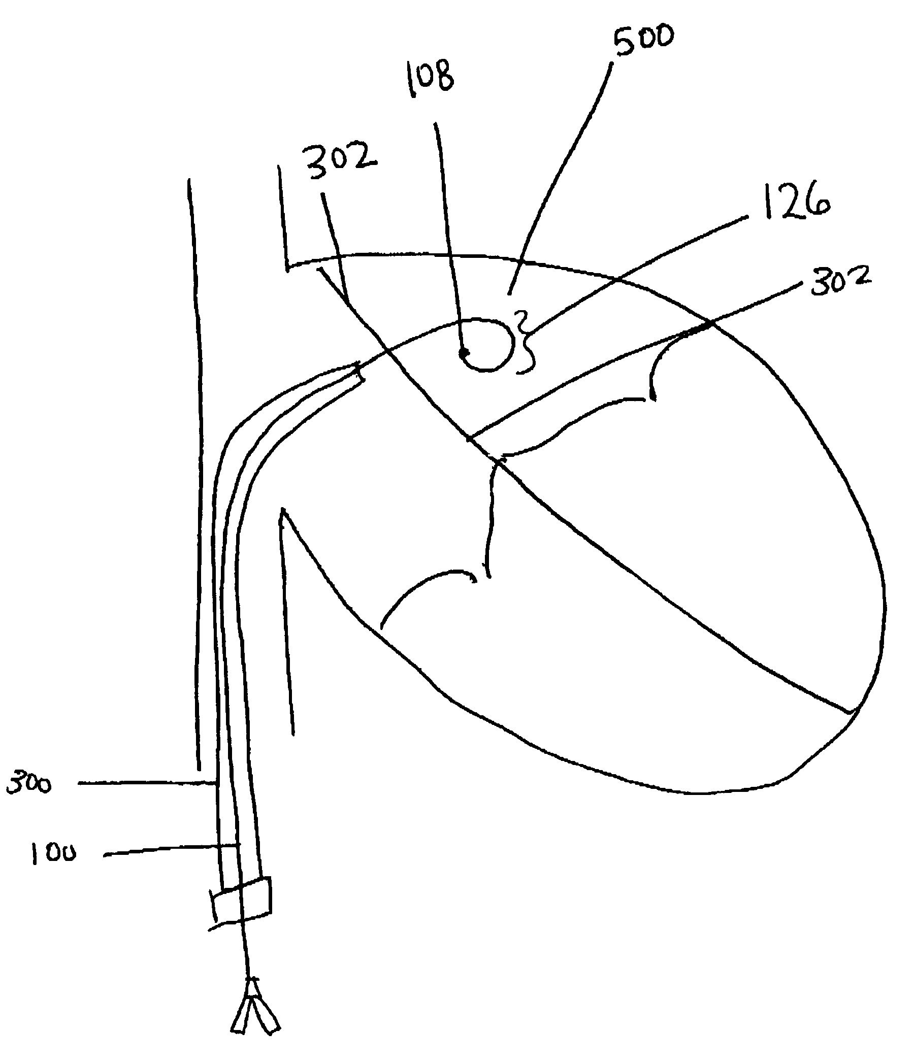
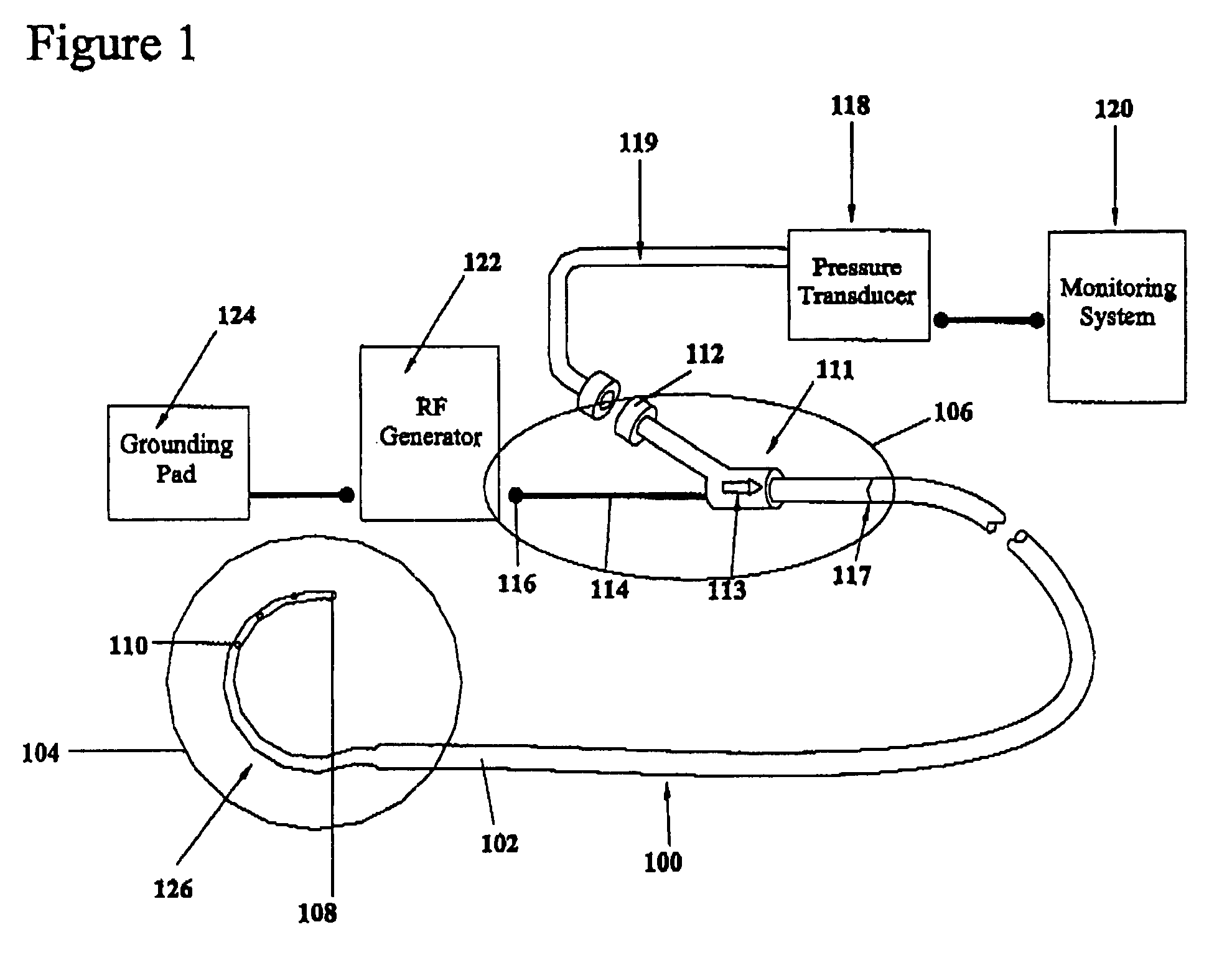
[0030]FIG. 1 illustrates a preferred embodiment of a transseptal device 100 in accordance with the invention. Transseptal device 100 comprises an elongate member 102 having a distal region 104, and a proximal region 106. The Distal region 104 is adapted to be inserted within and along a lumen of a body of a patient, such as a patient's vasculature, and maneuverable therethrough to a desired location proximate to septal tissue to be cut.

[0031]The elongate member 102 is typically tubular in configuration, having at least one lumen extending from the proximal region 106 to the distal region 104. Elongate member 102 is preferably constructed of a biocompatible polymer material that provides column strength. The elongate member 102 is sufficiently stiff to permit a soft guiding catheter to be easily advanced over the transseptal device 100 and through a perforation. Examples of suitable materials for the tubular portion of elongate member 102 are polyetheretherketone (PEEK), and polyimid...


PUM


Abstract

A device for creating a surgical perforation with a functional distal tip for creating a controlled perforation. The functional tip may comprise at least one active electrode for creating the perforation through the application of Radio Frequency (RF) energy. The device is curved in order to decrease the likelihood of injury to structures of a patient such as inadvertent cardiac perforation when used in transseptal perforation procedures. The device is introduced into the right atrium, and the functional tip is then positioned against the atrial septum. Energy is applied to create the perforation. The tip is advanced toward the left atrium to create the perforation and as it advances into the left atrium, the device takes on its curved shape to direct the tip away from cardiac structures. The position of the tip of the device can be determined in response to pressure sensed at the tip and determined by a monitor.

Description

TECHNICAL FIELD[0001]The invention relates to a device for creating a perforation in material of a patient such as the septum of the heart. More specifically, the invention relates to a device for creating a perforation in the material while minimizing the risk of inadvertent injury to other patient structures.BACKGROUND OF THE ART[0002]It is often required to create a perforation in the atrial septum to gain access to the left side of the heart interventionally to study or treat electrical or morphological abnormalities. It is also often desirable to create a hole in the atrial septum in patients with congenital heart defects in order to shunt the blood flow between the left and right sides of the heart to relieve high pressure or provide more blood flow to certain areas. Historically in these instances, a needle such as the Transseptal needle set of Cook Incorporated, Bloomington, Ind., USA is used. The needle is made of a stiff metal cannula, and has a sharpened distal tip. The n...

Claims


Application Information

Patent Timeline
Patent Type & Authority Patents(United States)
IPC IPC(8): A61B18/18A61B18/14A61B19/00
CPCA61B18/1492A61B2018/00351A61B2018/00601A61B2218/002A61B2018/00839A61B2019/464A61B2018/00702A61B2090/064
Inventor HARTLEY, AMANDA APRILSHAH, KRISHANVISRAM, NAHEEDBAYLIS, FRANK
Owner BOSTON SCI MEDICAL DEVICE LTD
Why Eureka
Try Eureka