
Picture signal contrast control

a picture signal and contrast control technology, applied in the field of picture signal contrast control, can solve the problems of difficult adjustment for an optimal response, cumbersome analog implementation, noise, etc., and achieve the effect of increasing the contrast of the pictur

Active Publication Date: 2006-05-23
DYNAMIC DATA TECH LLC
View PDF23 Cites 21 Cited by
  • Summary
  • Abstract
  • Description
  • Claims
  • Application Information

AI Technical Summary

Benefits of technology

[0009]The method may easily be implemented by digital circuits, whereby the advantages associated with digital circuits may be obtained.
[0010]By splitting the sub signal and reducing the chrominance followed by a reduction of the total color information an advantageous method may be obtained making it easy to implement and perform first the desaturation and then the contrast reduction.
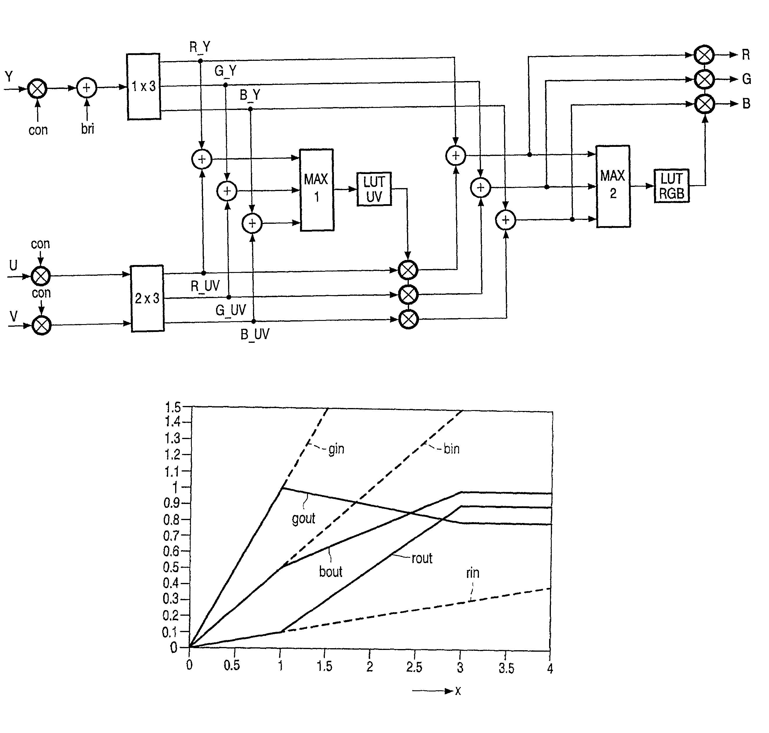
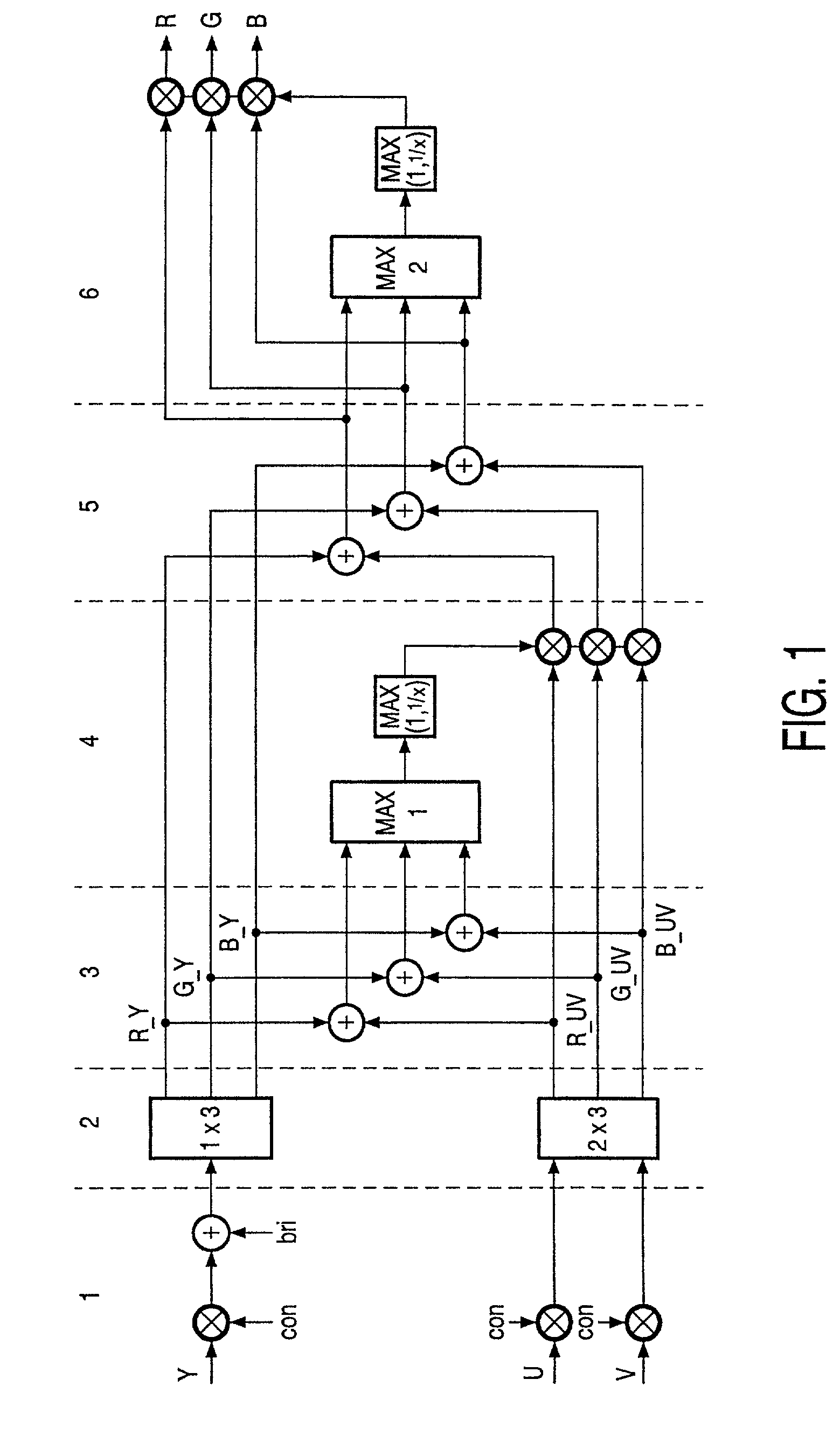
[0015]Thereby, so-called hard clipping may be obtained, resulting in that the amplitudes of the basic colors never exceed a maximum value. This is typically used to clip in small peaks in the picture such as subtitles.
[0016]Alternatively the first and / or said second value may decrease from 1 to a limit value. The limit value may be determined by multiplying the reciprocal of the amplitude value of the basic color having the highest amplitude with said predefined value. Thereby, softer clipping is obtained which i.e. could be used instead of hard clipping in larger areas of the picture in order to avoid distortion of these areas, i.e. areas such as faces.

Problems solved by technology

A problem with contrast amplification is that there is a contrast limit corresponding to the electronic video display or the D / A converter in the signal processor, meaning that the electronic video display is adapted to receive a limited range of input signals and the D / A converter in the signal processor is adapted to deliver a limited range of output signals.
Further an analog implementation is very cumbersome and noise sensitive, and it is hard to make adjustments for an optimum response.
Further the picture might lose details in the bright areas because of the clipping of the small peaks.

Method used


Image

  • Picture signal contrast control
  • Picture signal contrast control
  • Picture signal contrast control

Examples


Embodiment Construction

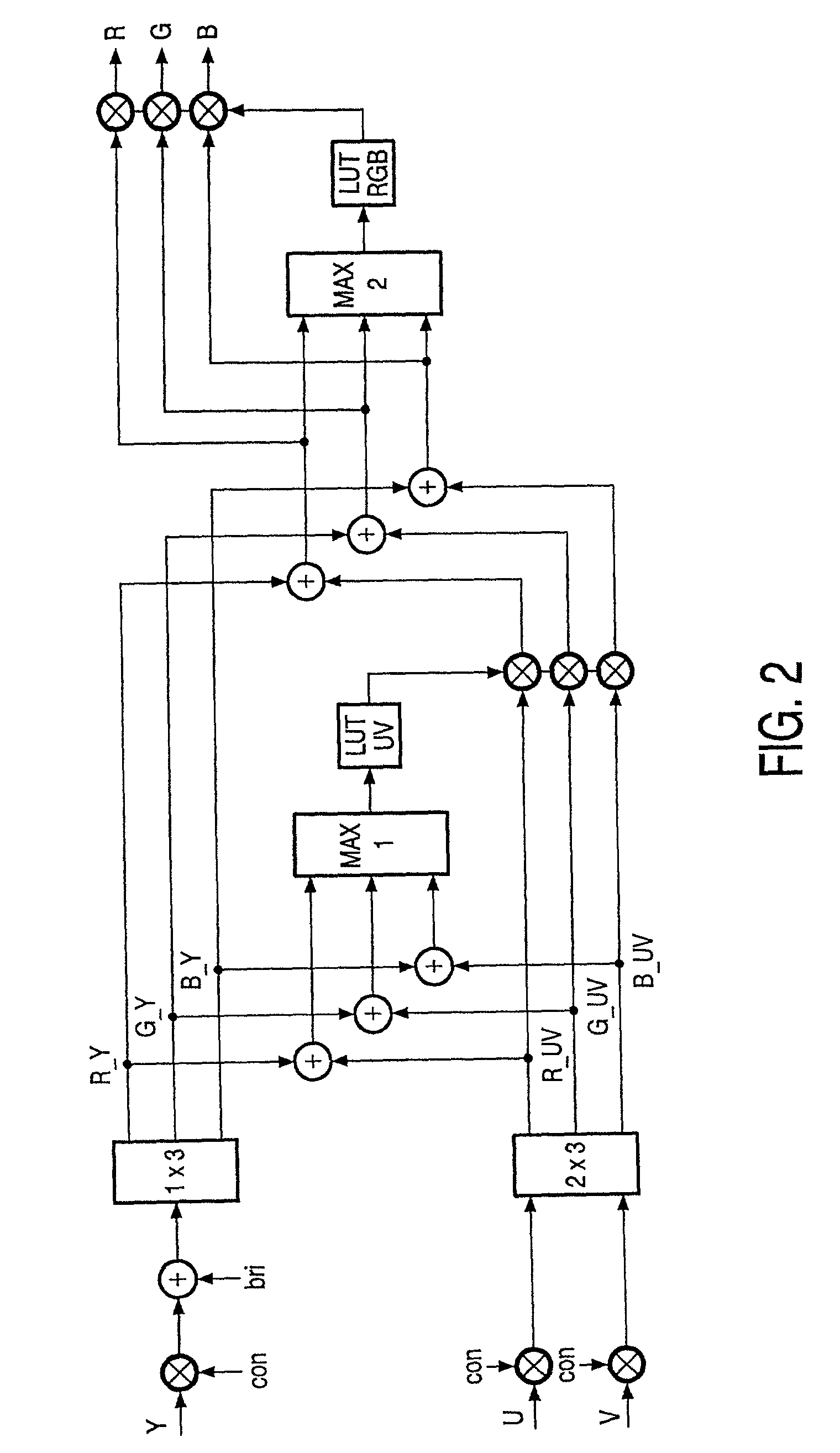
[0030]According to the present invention an advantageous method of controlling contrast in at least a group of sub signals in a picture (such as signal peaks) is by consecutively following the steps of:[0031]1. Reducing the saturation of the sub signals, i.e. by reducing the amplitude of those basic colors (U&V) in the sub signal to influence saturation of the picture.

[0032]Due to the violation of the “constant luminance principle”, a reduction of the saturation will make red and blue seem darker and cyan and yellow seem brighter. Therefore, although the amplitude of the largest of the 3 signals is reduced, reducing the saturation even increases the contrast.[0033]2. Reducing the contrast of the sub signals, i.e. by reducing the amplitude of all the basic colors (RGB or YUV) in the picture to influence contrast of the sub signals.

[0034]This reduces the intensity.

[0035]A third step could be introduced as a supplement to the above steps. This step reduces the contrast of the entire pi...


PUM


Abstract

The present invention relates to controlling contrast in at least part of a picture. The contrast control is performed by reducing the saturation (2–4) of the picture during contrast increase (1).

Description

FIELD OF THE INVENTION[0001]The present invention relates to controlling the contrast in a picture signal.BACKGROUND OF THE INVENTION[0002]A video signal for use as input to an electronic video display consists of a number of sub signals, each sub signal representing color information for different areas of the picture, and the color information is represented by basic colors, i.e. RGB (red, blue, green) or YUV (luminance & chrominance).[0003]If the viewer wants to amplify the contrast in a picture and thereby obtain a better light output from a display, this is done by boosting a weak signal (i.e. 50%) to nominal (i.e. 100%). There may still be 100% peaks in the signal that will now reach 200% of the permitted maximum level.[0004]A problem with contrast amplification is that there is a contrast limit corresponding to the electronic video display or the D / A converter in the signal processor, meaning that the electronic video display is adapted to receive a limited range of input sig...

Claims


Application Information

Patent Timeline
Patent Type & Authority Patents(United States)
IPC IPC(8): H04N5/52H04N5/57H04N9/68
CPCH04N9/68H04N23/86H04N9/77
Inventor STESSEN, JEROEN HUBERT CHRISTOFFEL JACOBUSVAN DALFSEN, AGE JOCHEM
Owner DYNAMIC DATA TECH LLC
Learn More