Image comparison apparatus, image comparison method, and program for causing computer to execute image comparison

a technology of image comparison and image, applied in the field of image comparison apparatus and image comparison, can solve the problems of counterfeiting methods, many troubles, counterfeiting of printed materials, etc., and achieve the effect of accurate and efficient comparison and observation and simple operation

Inactive Publication Date: 2006-05-23
OLYMPUS CORP
View PDF14 Cites 20 Cited by
  • Summary
  • Abstract
  • Description
  • Claims
  • Application Information

AI Technical Summary

Benefits of technology

[0012]The present invention provides an image comparison apparatus and image comparison method which can accurately and efficiently perform comparison and observation of a reference image and a comparison image with simple operation, and a program which causes a computer to execute image comparison.

Problems solved by technology

Recently, many troubles have been caused by counterfeiting of printed matter, counterfeiting of special printing / treatment on ID cards, and the like.
Counterfeiting methods associated with such troubles are so sophisticated as to make identification of counterfeits difficult.
In addition, printing or treatment for preventing counterfeiting becomes too elaborate to be checked by the human eye.
Therefore, an observer who has no specimen as a sample cannot perform comparing operation, and has a difficulty in counterfeit identification.
Such positioning, however, requires cumbersome operation, e.g., moving the positions of the specimens 204a and 204b on the stages 205a and 205b.
Since still images that have already captured (stored) are juxtaposed, a desired position on a reference image for comparison is difficult to adjust to a comparison image.
In addition, since images are simply arranged side by side, it is sometimes difficult to observe the differences between them.
When image files obtained by photography in the past are used for comparison, photographing conditions cannot often be known.
This makes it difficult to accurately compare and observe images.
Furthermore, since differences between two images are visually checked by the observer, an oversight and the like may occur.

Method used


Image

  • Image comparison apparatus, image comparison method, and program for causing computer to execute image comparison
  • Image comparison apparatus, image comparison method, and program for causing computer to execute image comparison
  • Image comparison apparatus, image comparison method, and program for causing computer to execute image comparison

Examples


first embodiment

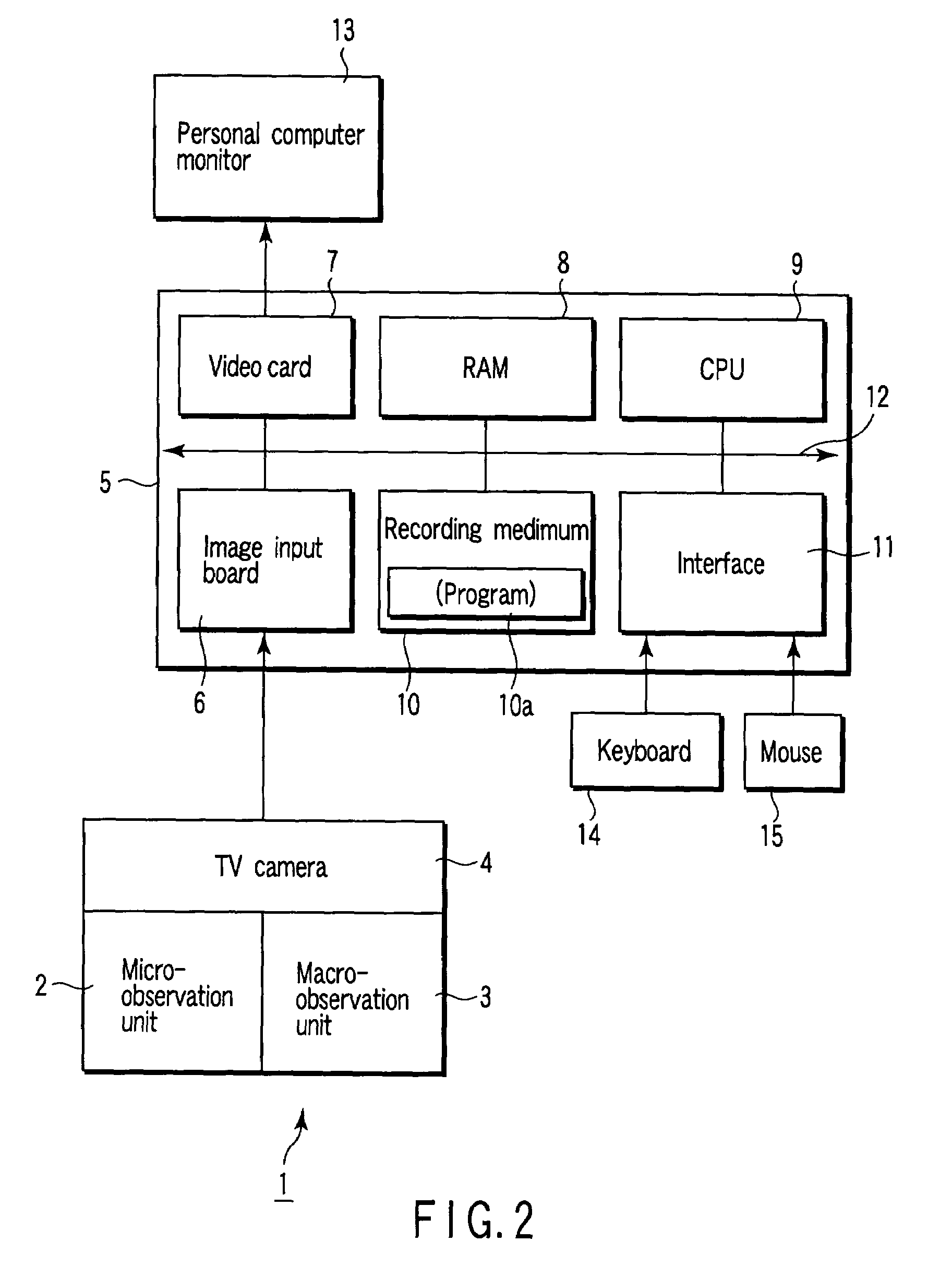
[0044]FIG. 2 is a block diagram showing a microscopic image comparison apparatus as an embodiment of an image comparison apparatus according to the present invention.

[0045]Referring to FIG. 2, an observation device 1 for observing a specimen (not shown) includes a micro-observation unit 2 which serves as a micro-observation image capturing means for capturing a microscopic observation image of the specimen so as to capture a microscopic observation image, a macro-observation unit 3 which serves as a macro-observation image capturing image for capturing a macroscopic observation image of the specimen, and a TV camera 4 serving as a photographing means. The observation device 1 sends out the observation image captured by the micro-observation unit 2 or macro-observation unit 3, as a digital image, to a personal computer body 5 serving as a control means through the TV camera 4.

[0046]The personal computer body 5 includes an image input board 6, video card 7, RAM 8, CPU 9, recording med...

second embodiment

[0087]The second embodiment of the present invention will be described with reference to FIG. 11.

[0088]The apparatus arrangement and GUI in the second embodiment are the same as those described in the first embodiment with reference to FIGS. 2, 3, and 4, and hence a description thereof will be omitted.

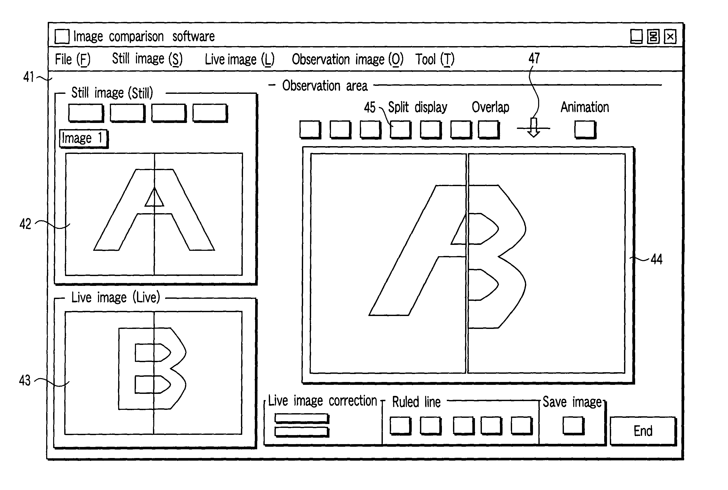
[0089]FIG. 11 shows an observation image displayed in an observation image display area 44 of a GUI 41 in FIG. 4. Referring to FIG. 11, a lattice 51 with a predetermined spacing is displayed on the observation image in the observation image display area 44. The lattice 51 may have a 9×6 matrix as shown in FIG. 11 and can be arbitrarily changed to, for example, a 2×2 matrix. With this arrangement, when a reference image in a still image display area 42 and a comparison image in a live image display area 43, which are described in the first embodiment, are displayed side by side, graphic patterns of the two images which are to be compared, the sizes of printed characters, positional rela...

third embodiment

[0090]The third embodiment of the present invention will be described with reference to FIG. 12.

[0091]When the above microscopic image comparison apparatus is used on a standalone basis, an image or information about a counterfeit print or the like as a specimen can be used in only this apparatus. Even if, therefore, for example, suspicious objects such as counterfeit prints are found in different places, e.g., various regions, it cannot be checked whether or not they are identical counterfeit prints. In addition, an image of an original print or the like must be captured in advance as a digital image in each microscopic image comparison apparatus by carrying an original specimen to each region. Such operation must be performed for all the microscopic image comparison apparatuses, and hence it takes much time, resulting in poor operation efficiency.

[0092]In the third embodiment, therefore, a plurality of microscopic image comparison apparatuses are connected to each other through a ...


PUM


Abstract

An image comparison apparatus includes an observation image capturing means for capturing at least one of a macroscopic observation image of a specimen and a microscopic observation image of the specimen, a photographing means for photographing an observation image captured by the observation image capturing means, a recording means for recording a reference image prepared in advance, and a display means for displaying the observation image photographed by the photographing means as a comparison image, and also displaying the reference image recorded on the recording means on the display means so as to allow comparison between the comparison image and the reference image.

Description

CROSS-REFERENCE TO RELATED APPLICATIONS[0001]This is a Continuation Application of PCT Application No. PCT / JP02 / 01364, filed Feb. 18, 2002, which was not published under PCT Article 21(2) in English.[0002]This application is based upon and claims the benefit of priority from the prior Japanese Patent Application No. 2001-041931, filed Feb. 19, 2001, the entire contents of which are incorporated herein by reference.BACKGROUND OF THE INVENTION[0003]1. Field of the Invention[0004]The present invention relates to an image comparison apparatus and image comparison method which compare a reference image as a sample with a comparison image as a comparison target, and a program for causing a computer to execute image comparison.[0005]2. Description of the Related Art[0006]Recently, many troubles have been caused by counterfeiting of printed matter, counterfeiting of special printing / treatment on ID cards, and the like. Counterfeiting methods associated with such troubles are so sophisticate...

Claims


Application Information

Patent Timeline
IPC IPC(8): G06K9/00G02B21/18G02B21/36
CPCG02B21/367G02B21/18
Inventor MORISHIMA, MASAHIROKAGAYAMA, AKITSUGUAOSHIMA, RYOJI
Owner OLYMPUS CORP
Why Eureka
Try Eureka