Routing control system, routing control device, and routing control method

Inactive Publication Date: 2009-05-19
NTT DOCOMO INC
View PDF21 Cites 3 Cited by
  • Summary
  • Abstract
  • Description
  • Claims
  • Application Information

AI Technical Summary

Benefits of technology

[0029]According to the present invention, the update of the routing control information is notified to the transfer device when the routing control information is updated by the control device. The transfer device can easily and quickly recognize that the transmitted temporary routing c

Problems solved by technology

The problems of a conventional packet communication system are: the routing control of packets on the network is complicated, and the expansion or reduction of the routing control function is difficult because the routing control function and the packet trans

Method used


Image

  • Routing control system, routing control device, and routing control method
  • Routing control system, routing control device, and routing control method
  • Routing control system, routing control device, and routing control method

Examples


first embodiment

[0041]A first embodiment of the present invention will now be described with reference to the accompanying drawings.

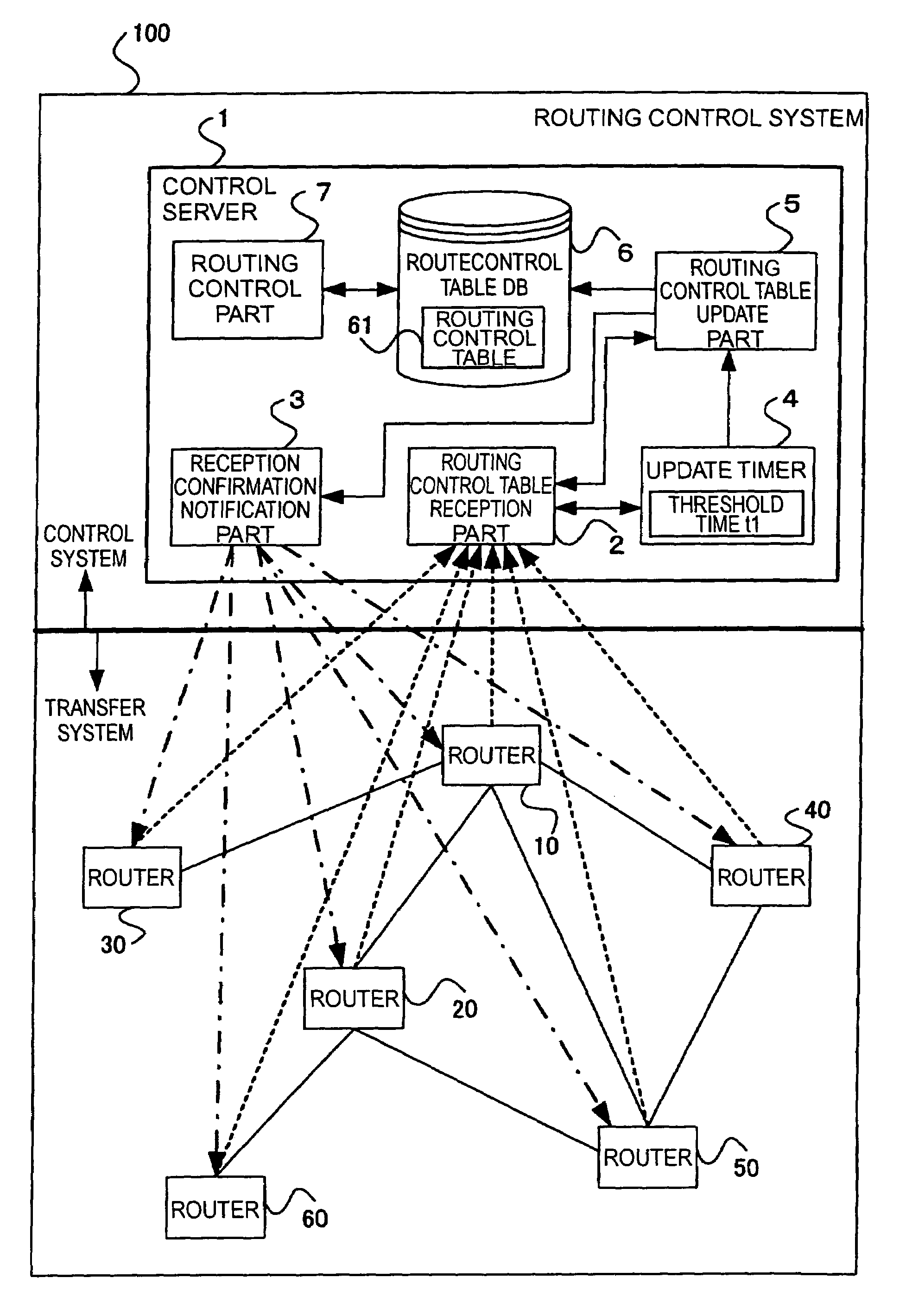
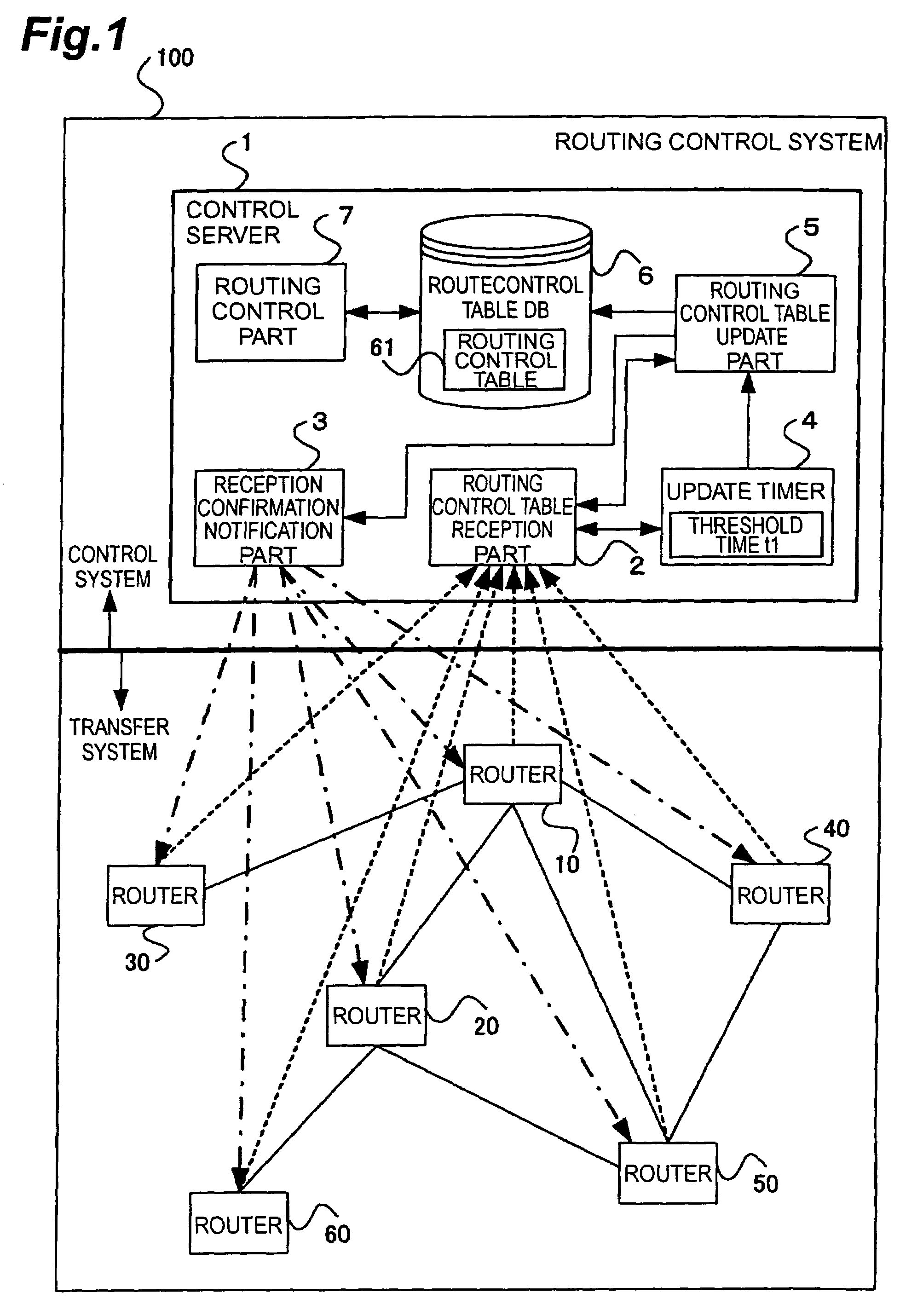
[0042]FIG. 1 is a diagram depicting a general configuration of the routing control system 100 according to the present invention and the functional configuration of the control server 1. As FIG. 1 shows, the routing control system 100 is comprised of a control server 1 (corresponds to the control device) which belongs to the control system, and routers 10-60 (corresponds to the transfer device) which belongs to the transfer system.

[0043]The control system and the transfer system are clearly separated by the control server 1 and the routers 10-60, which are physical elements of the routing control system 100. The control server 1 and each router 10-60 can mutually transmit / receive data via a wired link. The routers 10-60 can mutually transmit / receive data with another router via a wired link or a wired link and a router.

[0044]As FIG. 1 shows, the control server 1 compri...

second embodiment

[0082]The second embodiment of the present invention will now be described with reference to the accompanying drawings.

[0083]In the first embodiment, the control server of the control system has the update timer of the routing control table. Whereas in the present embodiment, the router of the transfer system has the update timer of the routing control table, so that the unnecessary transmission / reception of the routing control table between the control server and the router is decreased, and the communication load in the routing control system and the processing load of the control server are decreased.

[0084]The routing control system of the present embodiment will now be described.

[0085]FIG. 6 is a diagram depicting a general configuration of the routing control system 200 according to the present invention and a functional configuration of the control server 101. As FIG. 6 shows, the routing control system 200 is comprised of a control server 1 (corresponds to the control device)...


PUM


Abstract

The routing control system 100 according to the present invention comprises a control server 1 as the control system, and routers 10-60 as the transfer system. The control server 1 receives the temporary routing control table which is transmitted from the routers 10-60, and stores this temporary routing control table in the routing control table DB 6 as the routing control table of the router which is the transmission source. This routing control table is updated as needed when a predetermined time has elapsed from the previous update. The control server 1 refers to the data in the routing control table DB 6 constructed in this way, and performs the routing control of packets which pass through each router 10-60 on the network.

Description

BACKGROUND OF THE INVENTION[0001]1. Field of the Invention[0002]The present invention relates to a routing control system, routing control device, and routing control method.[0003]2. Related Background Art[0004]In a conventional packet communication system using a network, a router transfers packets based on the original routing control (routing) information created by itself. Each router existing in the system establishes a communication route of packets by exchanging routing control information with other routers. Because of this, the routing control function and the packet transfer function coexist in the router, and the router does not hold the entire routing control information on the packet communication system (e.g., reference is made to Nonpatent Document 1).[0005]Also depending on the routing system, the router may recalculate its own routing control information each time router control related information is exchanged with adjacent routers, so in this case, considerable lo...

Claims


Application Information

Patent Timeline
IPC IPC(8): H04L12/50H04L45/42H04Q3/00
CPCH04L12/24H04L41/00H04L45/00H04L45/42
Inventor JO, MANHEENISHIDA, KATSUTOSHIOKAGAWA, TAKATOSHISHINAGAWA, NORITERU
Owner NTT DOCOMO INC
Why Eureka
Try Eureka