Device connector

a technology for connecting devices and connectors, applied in the direction of connecting devices, threaded fasteners, bolts, etc., can solve the problems of unable to tighten bolts, bolts cannot be tightened smoothly, and the nut is applied with impulsive force, so as to prevent the nut from detachment, the effect of accurately and efficiently

Active Publication Date: 2015-03-19
SUMITOMO WIRING SYST LTD
View PDF4 Cites 3 Cited by
  • Summary
  • Abstract
  • Description
  • Claims
  • Application Information

AI Technical Summary

Benefits of technology

[0010]The detachment preventing plate is pushed while the moving rails are fit to and slid along the fixing rails, and an area of the detachment preventing plate near the escaping holes covers openings of the nut accommodating holes of the terminal block to prevent detachment of the nuts. A mating terminal in the case is placed on the terminal fitting supported on the terminal block and the bolt inserted through the bolt insertion holes is threadedly engaged with the nut and tightened by a tool to connect the terminals. The detachment preventing plate ensures that the nuts are retained for a long time despite repeated thermal expansion and contraction of the housing to be attached to the terminal block, as compared to nuts that merely are press-fit.
[0019]The invention reliably prevents detachment of nuts from nut accommodating holes after the nuts are arranged in a proper posture and enable a bolt fastening operation to be performed accurately and efficiently.

Problems solved by technology

Thus, the tip of a shaft of the bolt may apply an impulsive force to the nut.
The nut will incline with the terminal block so that an axial line of the nut may obliquely intersect with that of the bolt insertion hole of the terminal fitting so that the bolt cannot be tightened smoothly and, in an extreme case, it may not be possible to tighten the bolt.

Method used


Image

  • Device connector
  • Device connector
  • Device connector

Examples


Embodiment Construction

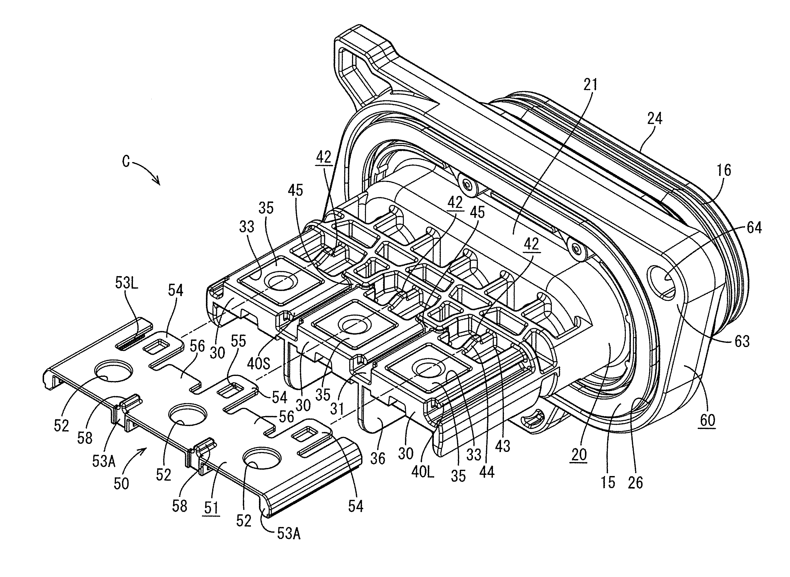
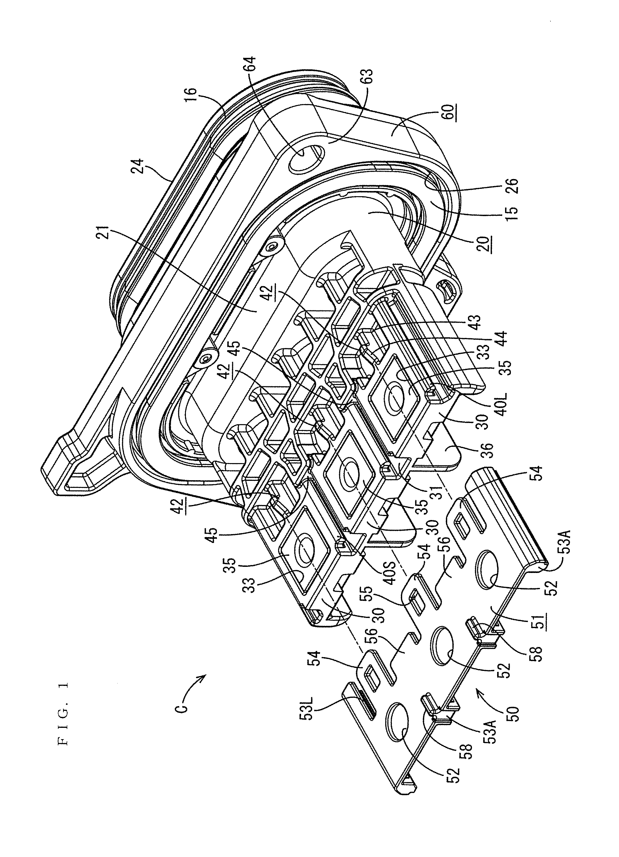
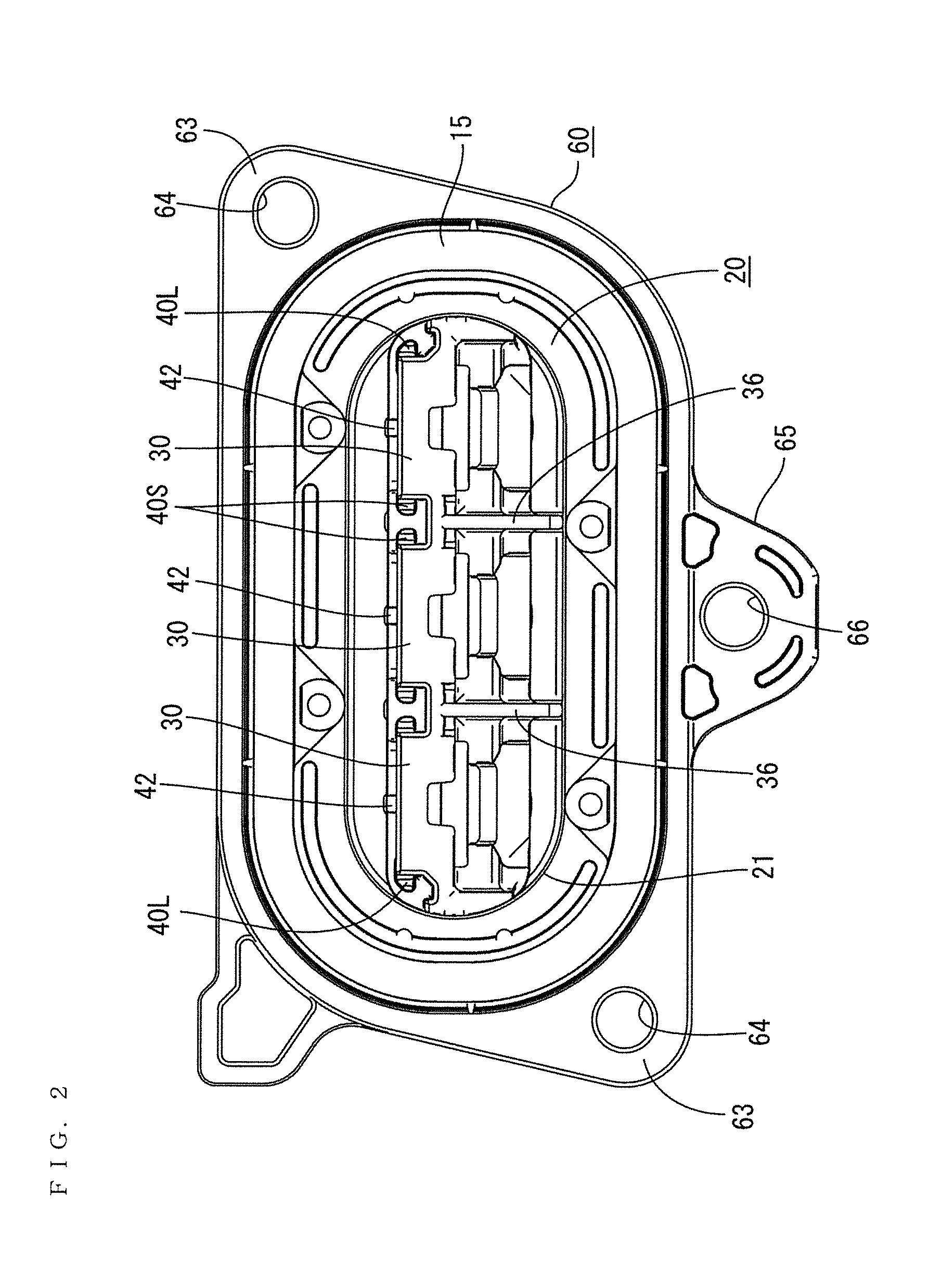
[0033]A first embodiment of the invention is illustrated in FIGS. 1 to 10. A device connector C of this embodiment is applied to supply power to a device, such as a motor or an inverter mounted in a hybrid vehicle, an electric vehicle or the like. As shown in FIG. 9, the device connector C is mounted to a metal-made case 1 of the device and a mounting hole 2 having an elliptical front view is formed to penetrate through this case 1.

[0034]The device connector C has terminal fittings 10 mounted in a housing 20 made of synthetic resin. As shown in FIG. 10, the housing 20 is mounted on an outer surface of the case 1, and tips of the terminal fittings 10 project into the case 1 through the mounting hole 2 while being supported on terminal blocks 30 projecting on the front of the housing 20. Mating terminals 5 in the case 1 are joined to the tips of the respective terminal fittings 10 by tightening bolts 8 and a wire-side connector (not shown) provided on an end of a harness is connected ...


PUM


Abstract

A device connector has a detachment preventing plate (50) mounted on surfaces of terminal blocks (30) to prevent detachment of nuts (35) and has escaping holes (52) at positions corresponding to nut accommodating holes (33) for allowing the tips of bolts (8) to escape. Fixed rails (40) are formed on the surface of each terminal block (30) at opposite sides of the nut accommodating hole (33) and extend in a projecting direction of the terminal block (30). Moving rails (53) are provided on a facing surface of the detachment preventing plate (50) and fit slidably to the fixed rails (40). The detachment preventing plate (50) is pushed and attached to cover the surfaces of the terminal blocks (30) from projecting ends of the terminal blocks (30) while the moving rails (53) are slid along and guided by the fixed rails (40).

Description

BACKGROUND[0001]1. Field of the Invention[0002]The invention relates to a device connector in which terminal fittings are connected to mating terminals by bolt fastening.[0003]2. Description of the Related Art[0004]U.S. Pat. No. 8,251,756 discloses a device connector with a housing and a plurality of busbar-like terminal fittings mounted side by side in the housing. Each terminal fitting has a bolt insertion hole on a tip. The tips of the terminal fittings project on one surface of the housing and can be supported on terminal blocks. Square nuts are press-fit in a rotation prevented manner in nut accommodating holes on the respective terminal blocks. This housing is mounted on an outer surface of a case of a device and, the terminal blocks are arranged to project into the case through mounting holes on the case.[0005]A busbar-like mating terminal fitting is placed on the upper surface of the terminal fitting supported on each terminal block, and also has a bolt insertion hole. The t...

Claims


Application Information

Patent Timeline
Patent Type & Authority Applications(United States)
IPC IPC(8): H01R4/34F16B41/00
CPCF16B41/002H01R4/34H01R9/18H01R13/502H01R4/301
Inventor TAKEMURA, AKIHIKO
Owner SUMITOMO WIRING SYST LTD
Why Eureka
Try Eureka