Circuit arrangement for switching a mobile radio transmitter between two modulation modes

a mobile radio transmitter and modulation mode technology, applied in the direction of multi-modulation transmitter/receiver arrangement, wireless communication, digital transmission, etc., can solve the problems of interference between the switching and modulation spectrum, timing problems also may arise, and unwanted effects

Active Publication Date: 2006-05-23
QUALCOMM INC
View PDF6 Cites 16 Cited by
  • Summary
  • Abstract
  • Description
  • Claims
  • Application Information

AI Technical Summary

Benefits of technology

[0022]Another advantage of the present invention is that the battery voltage modulator already provided in the prior art is used as an actuating element for the output power from the power amplifier. By providing the two cha...

Problems solved by technology

In this unwanted operating state, control loop instabilities and saturation effects can result in impairment of the switching and modulation spectrum.
Timing problems also may arise, since when its control limit has been reached the amplitude comparator requires a certain time in order to leave saturated operation; for example, if the output power Pa needs to be brought down at the end of a transmission time slot.
As such, both t...

Method used


Image

  • Circuit arrangement for switching a mobile radio transmitter between two modulation modes
  • Circuit arrangement for switching a mobile radio transmitter between two modulation modes

Examples


Embodiment Construction

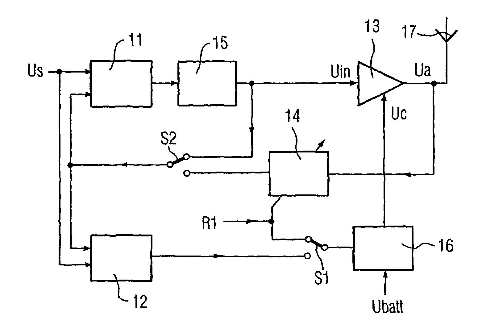
[0026]The inventive circuit contains the same main components as the circuit based on the prior art; namely, a phase comparator 11, an amplitude comparator 12, a power amplifier 13, an adjustable amplifier 14, a voltage controlled oscillator 15, a battery voltage modulator 16 and an antenna 17.

[0027]Both the phase comparator 11 and the amplitude comparator 12 are supplied with a nominal voltage Us as input signal. In addition, a present measured value for the output voltage Ua from the power amplifier 13 is fundamentally fed back to respective inputs on the phase comparator 11 and on the amplitude comparator 12. In contrast to the prior art, however, the present invention makes provision for a changeover switch S1 which can be switched between a first and a second position.

[0028]The position of the switching S1 governs which signal is applied to an input on the battery voltage modulator 16. In GMSK mode, the switch S1 adopts its first position, in which a control signal R1 for the a...


PUM


Abstract

A circuit is provided for regulating operation of a transmitter of a mobile communication terminal, which runs in the EDGE and GMSK modulation modes. The inventive circuit includes a power amplifier supplying an output signal for an antenna of the mobile communication terminal; a phase regulator that is provided with a phase comparator to which a setpoint signal for the output signal of the power amplifier is fed, and a voltage-controlled oscillator adjusting the phase position of the output signal of the power amplifier, the phase regulator regulating the phase position of the output signal of the power amplifier; an amplitude-regulating device that is provided with an amplitude comparator to which the setpoint signal for the output signal of the power amplifier is fed, and a battery-powered battery-voltage modulator adjusting the amplitude of the output signal of the power amplifier, the amplitude-regulating device regulating the amplitude of the output signal of the power amplifier; and a feedback line feeding an actual measured value for the output signal of the power amplifier back to the phase comparator and the amplitude comparator, the feedback line being provided with an adjustable amplifier which is controlled by a baseband chip and sets an output power of the antenna. The inventive circuit includes a changeover switch which is wired in such a way that it connects an input of the battery-voltage modulator to an output of the amplitude comparator in a first position for the EDGE mode while connecting an input of the battery-voltage modulator to an output of the power amplifier in a second position for the GMSK mode, the connection being made via the adjustable amplifier in both positions.

Description

BACKGROUND OF THE INVENTION[0001]The present invention relates to a circuit for controlling operation of a transmitter in a mobile communication terminal, which transmitter is designed for the modulation modes EDGE and GMSK, having:[0002]a power amplifier which delivers an output signal for an antenna on the mobile communication terminal;[0003]a phase controller, which has a phase comparator, to which a nominal signal for the output signal from the power amplifier is supplied, and a voltage controlled oscillator for aligning the phase of the output signal from the power amplifier, for controlling the phase of the output signal from the power amplifier;[0004]an amplitude controller, which has an amplitude comparator, to which the nominal signal for the output signal from the power amplifier is supplied, and a battery voltage modulator, powered by a battery, for aligning the amplitude of the output signal from the power amplifier, for controlling the amplitude of the output signal fro...

Claims


Application Information

Patent Timeline
IPC IPC(8): H04B1/04H04M1/00H04B1/40H04L27/00H04W88/06
CPCH04B1/04H04W88/06H04L27/0008H04B1/406
Inventor HERZBERG, RALFNAGEL, JORG
Owner QUALCOMM INC
Why Eureka
Try Eureka