Autonomous gas powered ram

a gas-powered ram and ram technology, applied in the direction of engine components, engine starters, fluid-pressure actuators, etc., can solve the problem of reducing reliability

Inactive Publication Date: 2006-05-30
DAUNAS YVES
View PDF22 Cites 5 Cited by
  • Summary
  • Abstract
  • Description
  • Claims
  • Application Information

AI Technical Summary

Benefits of technology

[0004]As embodied and broadly described herein, the invention provides an autonomous gas powered ram. The ram comprises a first body that defines a first internal cavity and a first piston mounted within the first internal cavity. The first piston is attached to an actuator and is operative for moving the actuator between a first operative position and a second operative position in relation to the first body. The second operative position is different than the first operative position. The ram further comprises a second body that is mounted within the first internal cavity. The second body comprises a second internal cavity, an explosive charge and a second piston. The second internal cavity is defined by an internal wall that comprises a locking portion. The explosive charge is also located in the second internal cavity and is adapted for detonating in response to an impulse. The second piston is located within the second internal cavity and is attached to a rod. The second piston is operative for causing the rod to move from a first position to a second position in response to the detonation of the explosive charge. The displacement of the rod from the first position to the second position causes the actuator to move towards the second operative position, and in the second position the rod is engaged with the locking portion of the second body in order to prevent the actuator from returning to the first operative position.

Problems solved by technology

This approach is unsatisfactory because of the inherent complexity of the systems using these types of powered sources which reduces their reliability.

Method used


Image

  • Autonomous gas powered ram
  • Autonomous gas powered ram
  • Autonomous gas powered ram

Examples


first embodiment

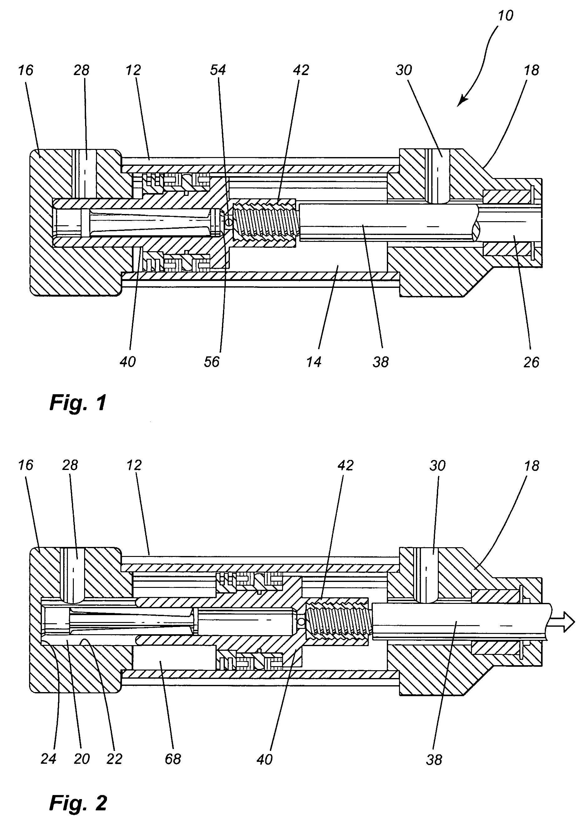
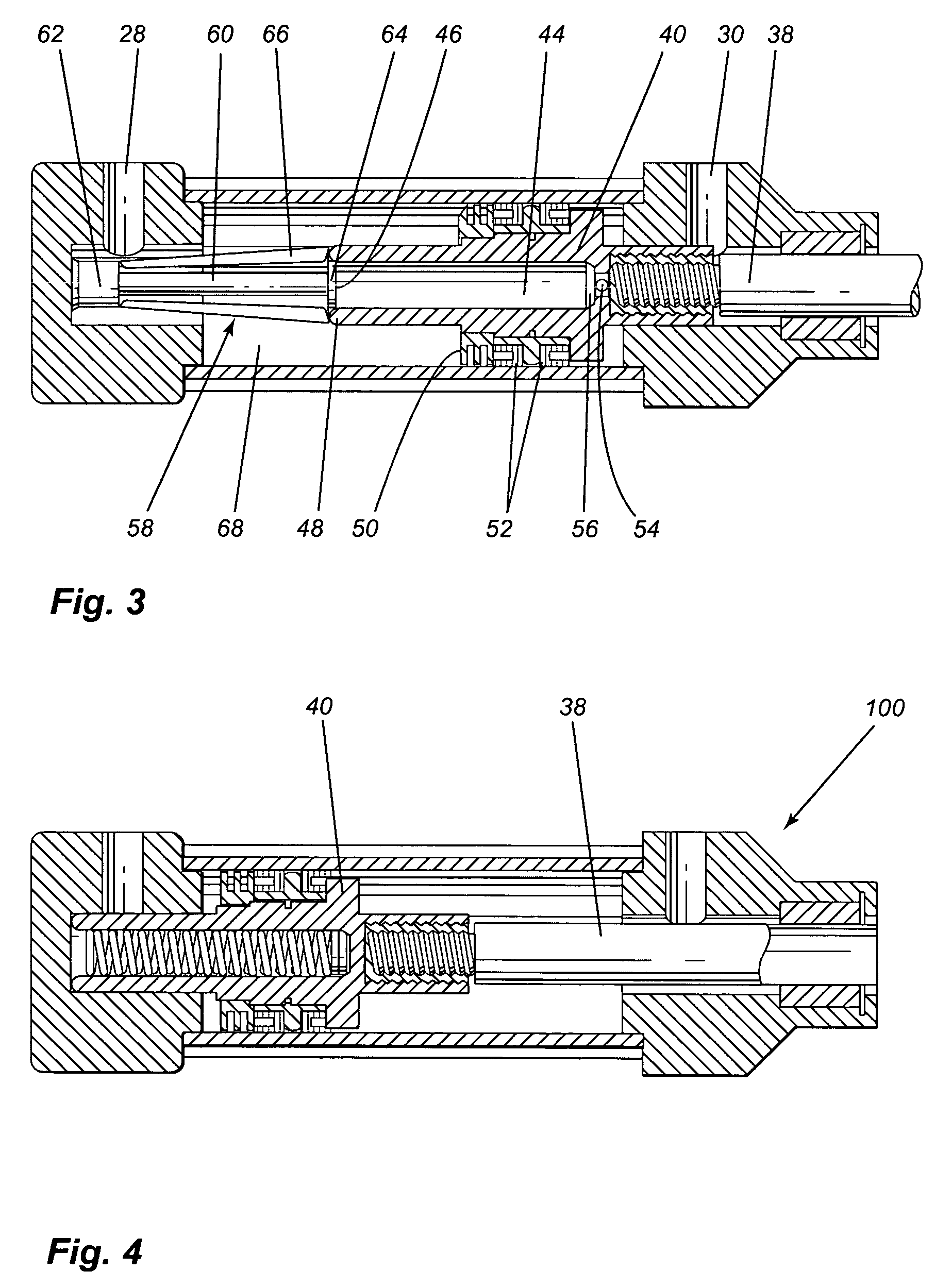
[0026]With reference to FIGS. 1 to 3, an autonomous gas powered ram constructed in accordance with the invention is identified by the reference numeral 10.

[0027]Autonomous gas powered ram 10 can be incorporated to any component such as an elevator, a crane, a lift, a door, a gate, wheels, gears or breaking devices for stopping the movement of a component upon detection of an operation failure, a fire or a hazardous operation condition.

[0028]For example, autonomous gas powered ram 10 can stop the movement of an elevator, a gate or a lift upon detection of a rupture of a cable. It can also keep the doors of a building in their open position upon detection of a fire so as to permit the evacuation of people situated in the building through the open doors. It can stop the movement of a seat upon detection of a vehicle collision. It can stop the movement of a vehicle upon detection of a failure of its breaking system, or it can keep the doors of a building or an armored truck in the close...

fourth embodiment

[0047]Shown in FIGS. 8 to 10 is an autonomous ram 300 in accordance with the present invention.

[0048]Autonomous ram 300 comprises a first body 302 having a first internal cavity 304. The first body 302 comprises a central portion 305, a first end portion 306 and a second end portion 308, which as shown in FIGS. 8 to 10 can be separate parts that are connected together to form the first body 302. In an alternative embodiment, the central portion 305, first end portion 306 and second end portion 308 can be formed as one integral component. It will be appreciated that the first body 302 can be made of a variety of different materials, and can be made in a variety of different shapes, without departing from the spirit of the invention.

[0049]As shown in FIGS. 8 to 10, the first end portion 306 of the first body 302 includes a cap 310 that is removably connected to the first body 302 via threads. The second end portion 308 defines a passageway 312 that communicates with the exterior of th...

fifth embodiment

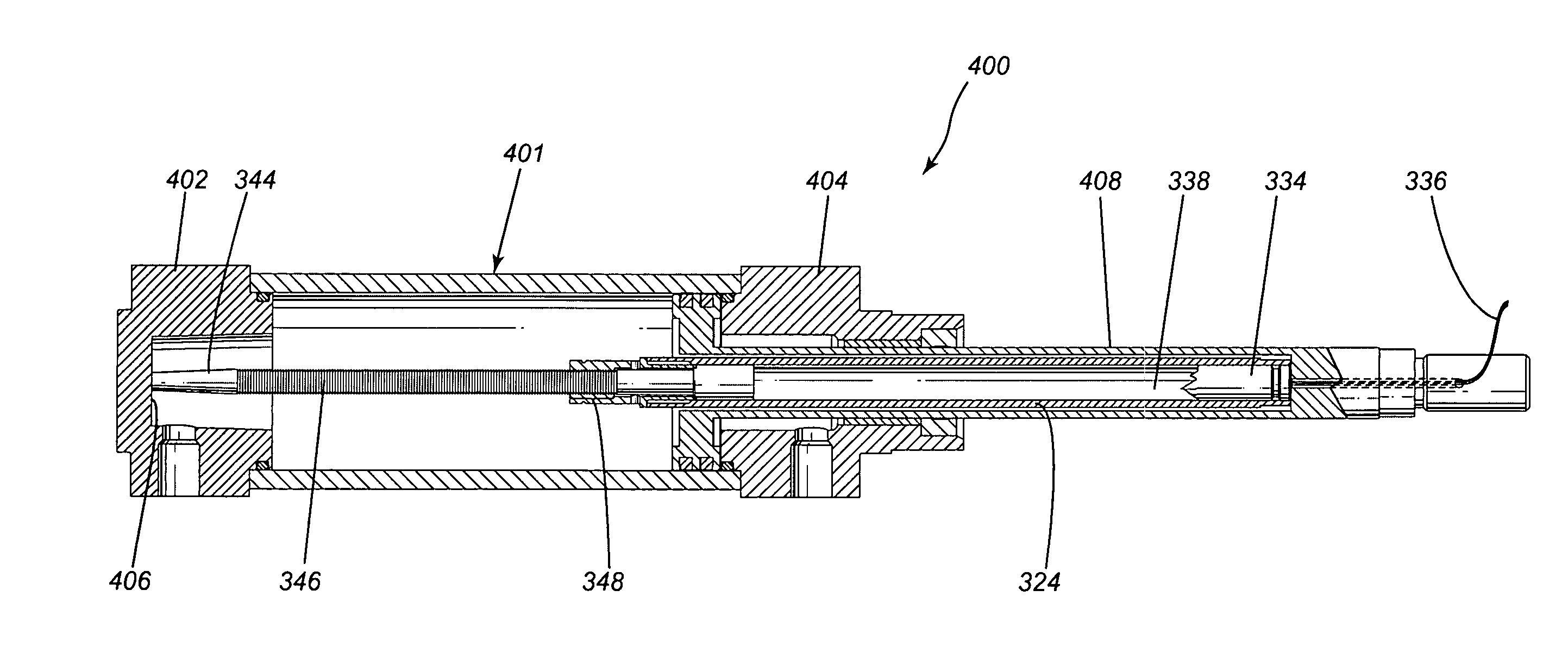
[0069]In this fifth embodiment, the first body 401 comprises a first end portion 402 that defines an abutment surface 406. The second body 324 is adapted for being mounted to the actuator 408 that is attached to first piston 314. FIG. 11 shows the first piston 314 and actuator 408 in the first operative position.

[0070]The explosive charge 334 contained within second body 324 is operative to detonate in response to an impulse, which in the example of implementation shown in FIGS. 11 to 13 is received from the wires 336 that extend through actuator 408. In operation, when the explosive charge 334 detonates, and the second piston 330 is displaced due to the gas pressure created within detonation chamber 338, the rod 332 is operative to move in the direction indicated by arrow 410 shown in FIG. 12. Once the tip 344 of rod 332 abuts against abutment surface 406 of the main body 401, the continuing pressure on second piston 330 causes the second body 324 to start moving in the direction o...


PUM


Abstract

The present invention provides an autonomous ram that comprises a first body having a first internal cavity and a first piston mounted therein. The first piston is attached to an actuator for moving the actuator between a first operative position and a second operative position. The ram further comprises a second body mounted within the first internal cavity. The second body comprises a second internal cavity that is defined by an internal wall having a locking portion. An explosive charge is located in the second internal cavity and is adapted for detonating in response to an impulse. A second piston located within the second internal cavity is operative for causing a rod to move from a first position to a second position in response to the detonation of the explosive charge. The displacement of the rod causes the actuator to move towards the second operative position. In the second position the rod is engaged with the locking portion of the second body.

Description

CROSS REFERENCE TO RELATED APPLICATIONS[0001]The present application is a continuation-in-part of patent application Ser. No. 09 / 978,675 filed on Oct. 18, 2001 now U.S. Pat. No. 6,655,143 claiming priority upon Canadian application serial No. 2,355,504 filed on Aug. 17, 2001. The contents of the above documents are incorporated herein by reference.FIELD OF THE INVENTION[0002]The present invention relates to an autonomous gas powered ram comprising an actuator that is movable from a first operative mode to a second operative mode, movement of the actuator towards the second operative mode is caused by the detonation of an explosive charge located within the ram.BACKGROUND OF THE INVENTION[0003]In many mechanical systems, it is often necessary to provide an actuator that can be used to activate a certain component or functions when an emergency arises. One specific example is to bring an elevator car to a stop. Current available technologies accomplish this task by using electrically,...

Claims


Application Information

Patent Timeline
Patent Type & Authority Patents(United States)
IPC IPC(8): F01B29/08F15B15/19F15B15/26
CPCF15B15/261F15B15/19
Inventor DAUNAS, YVES
Owner DAUNAS YVES
Why Eureka
Try Eureka