
Balanced orifice plate

Active Publication Date: 2006-05-30
NASA
View PDF31 Cites 110 Cited by
  • Summary
  • Abstract
  • Description
  • Claims
  • Application Information

AI Technical Summary

Benefits of technology

[0010]Accordingly, it is an object of the present invention to provide an orifice plate for installation in a conduit where one process variable associated with a fluid flow passin

Problems solved by technology

None of the prior art teach an orifice plate designed to equalize or balance one or more process variables across the entirety of the plate's surface area.
In general, the variation of a process variable across an orifice plate's surface introduces inefficiencies in a fluid flow.
For example, prior art orifice plates generally experience fairly large pressure losses as a fluid flows from one side of the plate to the other.
Unfortunately, the typical way of dealing with such large pressure losses is to use larger and more expensive fluid pumps.
Also, pressure potential in prior art orifice plates is generally consumed by eddy turbulence that is random and chaotic.
These eddy formations about the orifice plate reduce linearity and repeatability of any process variable measurements thereby causing a reduction in measurement accuracy.
Reduced measurement accuracy leads to processes that are highly variable which, in turn, increases process costs due to greater equipment operational margins that must be maintained.

Method used


Image

  • Balanced orifice plate
  • Balanced orifice plate
  • Balanced orifice plate

Examples


Embodiment Construction

)

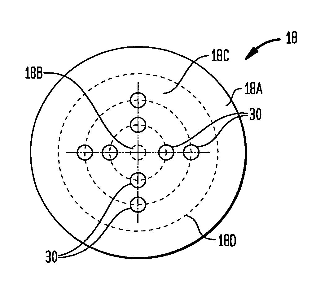
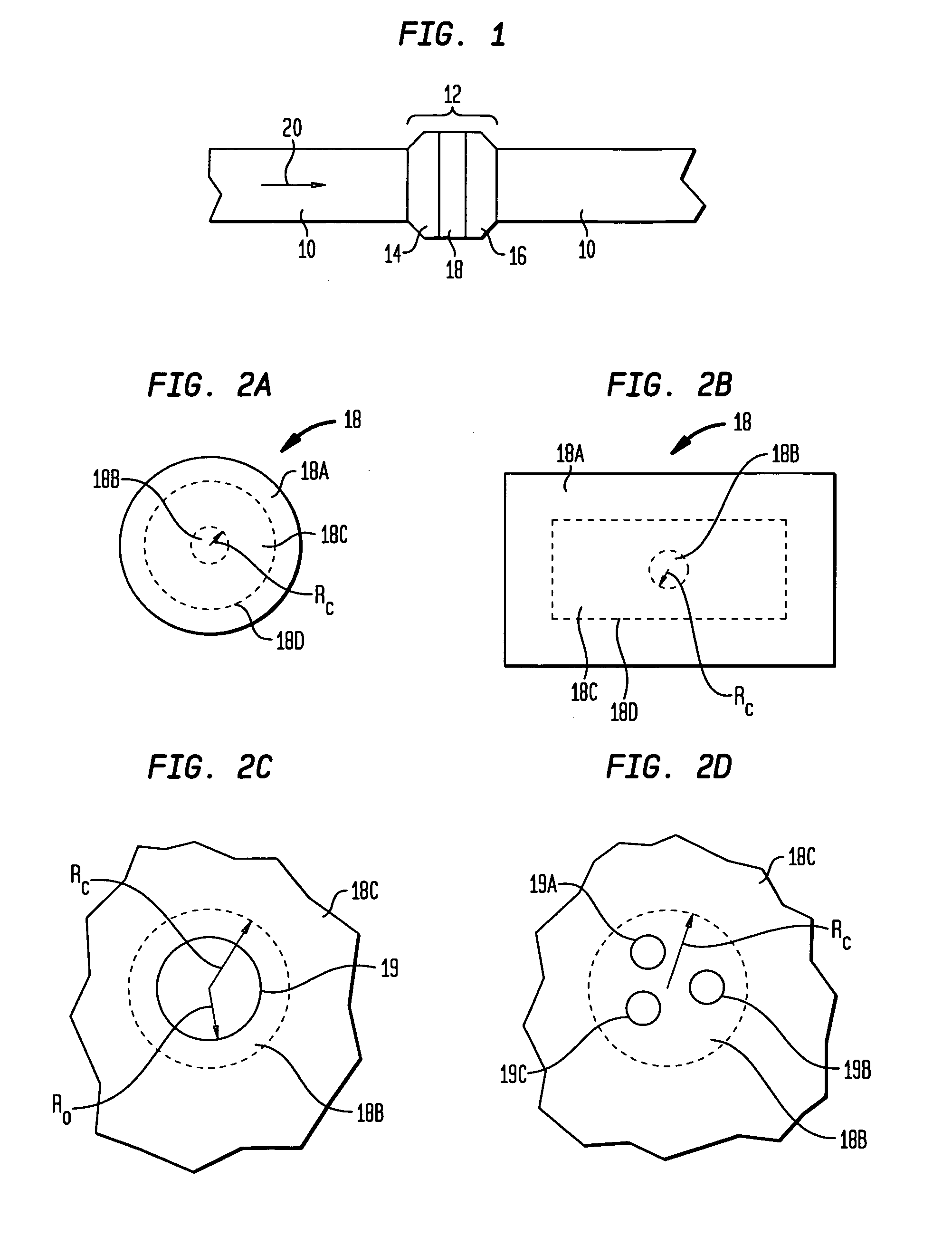
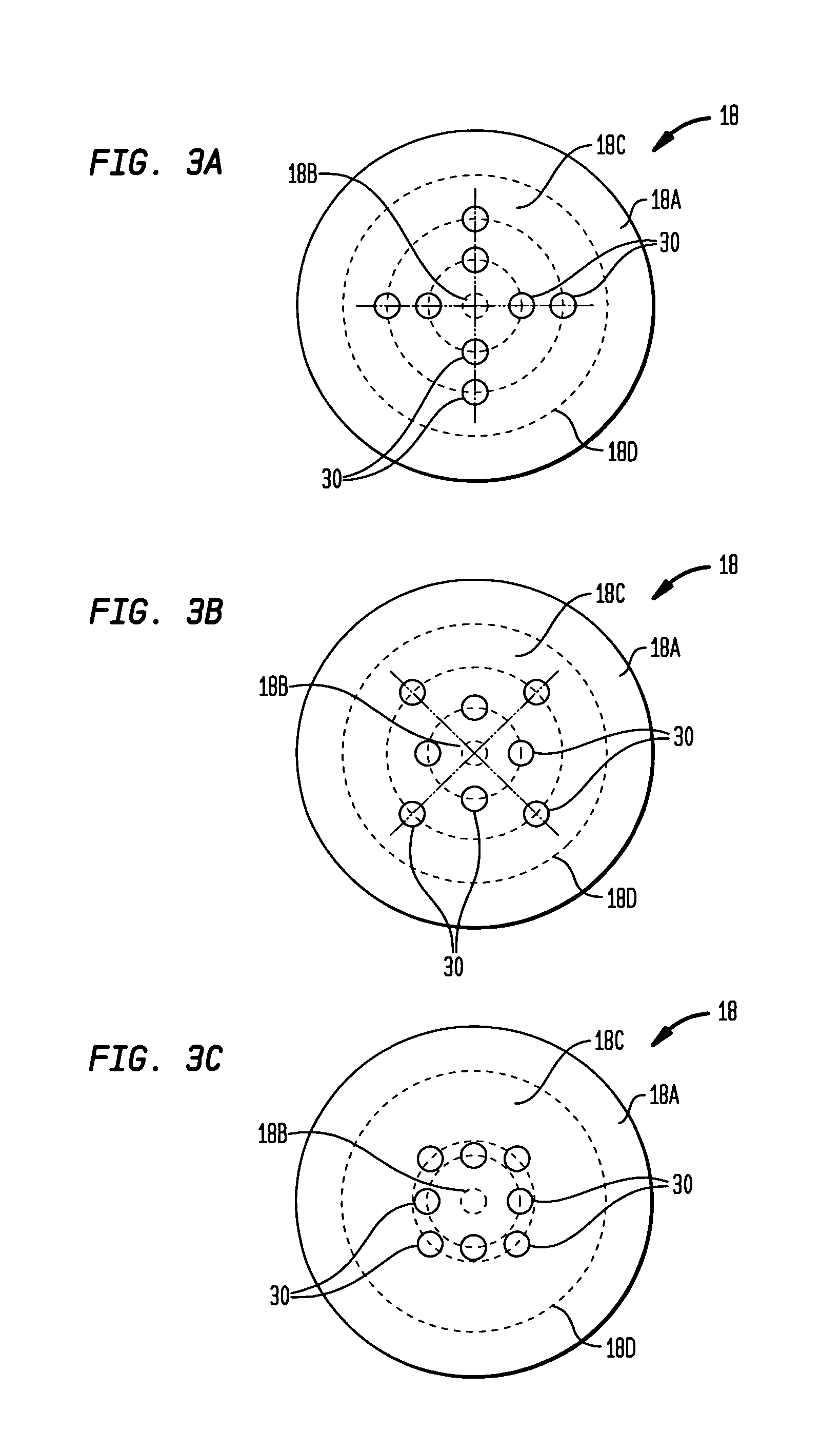
[0033]The present invention is an improved orifice plate. As used herein, the term “orifice plate” includes any structural element (e.g., plate, disk, block, etc.) having a hole pattern formed therethrough that is to be installed in a fluid flow such that the fluid passes through the element's hole pattern. While the orifice plate can be used in a flowmeter, it could also be used simply as a flow conditioner designed to modify a fluid flow in some fashion, e.g., straighten a flow, reduce noise associated with a flow, reduce vibration associated with a flow, etc.

[0034]In terms of using the orifice plate in a flowmeter, the present invention provides for more accurate process variable measurements and reduces costs associated with running such a process. The orifice plate of the present invention reduces eddies, turbulent shear and fluid-flow stresses that otherwise contribute to pressure loss, noise, and other inefficiencies. Accordingly, the orifice plate of the present invention p...


PUM


Abstract

An orifice plate for use in a conduit through which fluid flows is defined by a central circular region having a radius R0 and a ring-shaped region surrounding the central circular region. The ring-shaped region has holes formed therethrough with those holes centered at each radius R thereof satisfying a relationshipAR=a / (XRVRb)whereAR is a sum of areas of those holes having centers at radius R,XR is a flow coefficient at radius R,VR is a velocity of the fluid that is to flow through the conduit at radius R,b is a constant selected to make at least one process variable (associated with the fluid that is to flow through the conduit) approximately equal at each radius R, anda is a constant that is equal to (XRARVRb) at each radius R.

Description

ORIGIN OF THE INVENTION[0001]The invention was made in part by an employee of the United States Government and may be manufactured and used by or for the Government of the United States of America for governmental purposes without the payment of any royalties thereon or therefor.BACKGROUND OF THE INVENTION[0002]1. Field of the Invention[0003]This invention relates to flow control devices. More specifically, the invention is an orifice plate that, when inserted into the cross section of a fluid flow, balances or equalizes one or more process variables associated with the flow across the surface of the plate.[0004]2. Description of the Related Art[0005]There are numerous applications utilizing fluid flow in a conduit where one or more process variables associated with a fluid flow (e.g., pressure, temperature, mass flow, etc.) must be modified or measured. Accordingly, a variety of orifice plates have been developed for use as flowmeters, flow controllers, flow limiters, or simply for...

Claims


Application Information

Patent Timeline
IPC IPC(8): F15D1/02G01F1/42
CPCG01F1/42F15D1/02
Inventor KELLEY, ANTHONY R.VAN BUSKIRK, PAUL D.
Owner NASA
Learn More