Data reader for multi-mode operation

a data reader and multi-mode technology, applied in the field of data readers, can solve the problems of reducing the likelihood of inadvertent scanning, tighter aiming requirements, and inferior performance of barcode scanners designed for one mode of operation, so as to minimize the manipulation of the scanner, and improve the accuracy of scanning.

Inactive Publication Date: 2006-05-30
DATALOGIC SCANNING
View PDF73 Cites 20 Cited by
  • Summary
  • Abstract
  • Description
  • Claims
  • Application Information

AI Technical Summary

Benefits of technology

[0012]In one preferred embodiment, a single set of pattern generating optics is employed to simultaneously project a plurality of scan patterns, one scan pattern optimized for fixed performance and one scan pattern optimized for portable performance. In another embodiment, a single set of pattern generating optics is switched between a scan pattern optimized for fixed mode reading and a scan pattern optimized for portable mode reading. In one preferred embodiment, separate and distinct scan pattern generating optics are employed, thereby allowing independent optimization of the performance characteristics of the barcode scanner for each mode of operation.
[0013]A barcode scanner of one or more of the preferred embodiments may offer the advantage of flexibility for the end user, in that one device can be used in multiple modes of operation without suffering from inferior performance characteristics of previously available fixed / portable barcode scanners. The device described herein exhibits performance characteristics in each mode of operation comparable to those of barcode scanners designed for only one mode of operation or the other. The multiple aperture embodiment may also minimize the manipulation of the scanner required for a user to aim the scanner when the scanner is in portable mode and allowing the user to easily return the scanner to fixed mode.

Problems solved by technology

The reduced angular field of view reduces the likelihood of inadvertent scanning of other barcode labels, but in turn leads to tighter aiming requirements.
Previously this combined operation has been accomplished by compromising among the various requirements for fixed and portable modes of operation, yielding a barcode scanner which can be used in both modes of operation but with performance inferior to barcode scanners designed for one mode of operation only.

Method used


Image

  • Data reader for multi-mode operation
  • Data reader for multi-mode operation
  • Data reader for multi-mode operation

Examples


Embodiment Construction

[0036]Preferred embodiments will now be described with reference to the drawings. For clarity of description, any identifying numeral representing an element in one figure will represent the same element when used in any other figure.

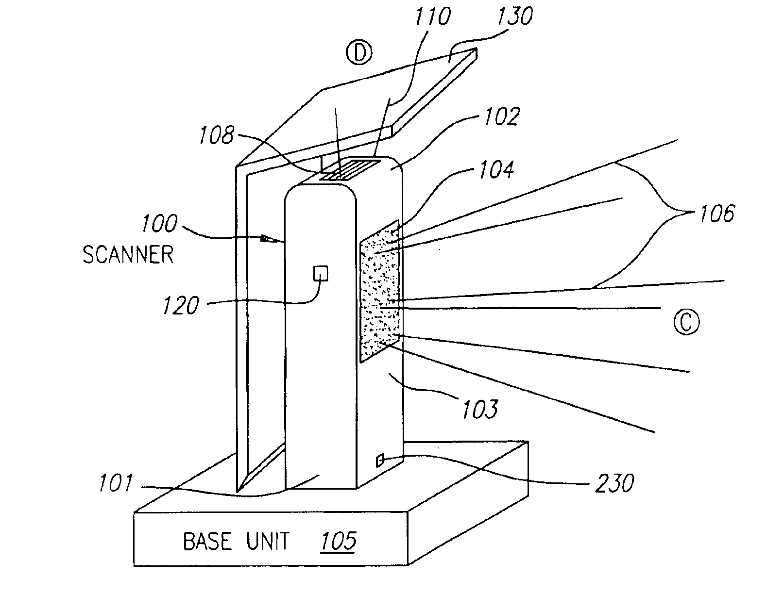
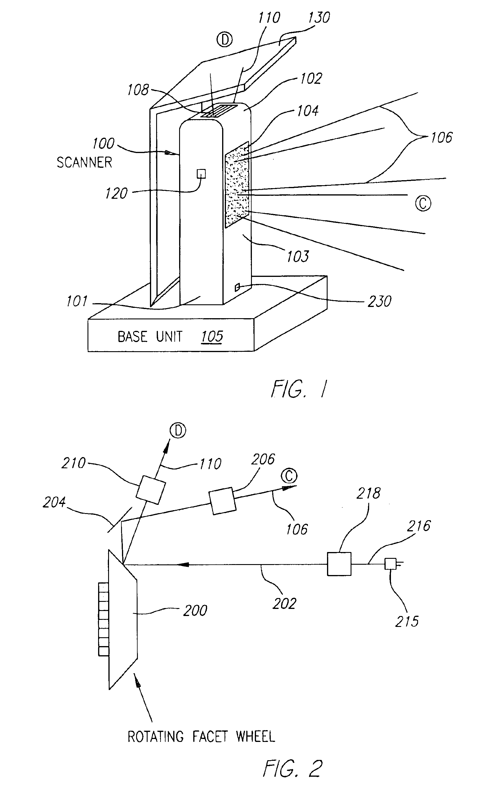
[0037]FIGS. 1-2 illustrate a preferred embodiment of a multiple-mode data reading device, in this embodiment a bar code scanner 100. The barcode scanner 100 includes a top portion 102 and a bottom portion 101. The scanner 100 rests on a base unit 105. A first scan window 104 is shown on the front side 103 of the barcode scanner 100 through which a first scan pattern 106 is projected into a first scan volume C in front of the first scan window 104. A second scan window 108 is positioned on the top portion 102 of the barcode scanner 100 through which a second scan pattern 110 is projected into a second scan volume D in front of the second scan window 108.

[0038]The barcode scanner 100 is placed in base unit 105 which supports the scanner for operation in t...


PUM


Abstract

A data reader and method for data reading, such as a barcode scanner, wherein the scan pattern generating optics and other features are optimized for different modes of operation. In a preferred embodiment, different patterns are projected from different apertures in the scanner housing, one scan pattern optimized for handheld operation and the other optimized for fixed operation. Other optimizable features include the presence or absence of an aiming beam, which may be generated from the same laser source as the scan pattern or from another source, and enabling or disabling decoding of the signal received signal during a portion of a facet wheel rotation. Decoding may be disabled while the scan line(s) for handheld use is generated unless a switch or trigger is actuated.

Description

RELATED APPLICATIONS[0001]This application is a continuation of application Ser. No. 10 / 418,988 filed Apr. 18, 2003 Pat. No. 6,719,201, which is a continuation of application Ser. No. 08 / 792,829 filed Jan. 30, 1997 Pat. No. 6,575,368, which claims the benefit of U.S. Provisional application of Ser. No. 60 / 010,935 filed Jan. 31, 1996.BACKGROUND[0002]The field of the present invention relates to data readers, such as scanners and bar code reading devices. In particular, barcode readers are described herein which may be used in both fixed and handheld scanning applications by utilizing distinct optical scan patterns for fixed operation and handheld operation. Each scan pattern is optimized for its respective mode of operation, thereby avoiding performance degrading compromises necessary when a single scan pattern is used for both modes of operation.[0003]A barcode label comprises a series of parallel dark bars of varying widths with intervening light spaces, also of varying widths. The...

Claims


Application Information

Patent Timeline
Patent Type & Authority Patents(United States)
IPC IPC(8): G06K7/10G06K9/22
CPCG06K7/10584G06K7/10613G06K7/10881G06K7/109G06K7/10693G06K2207/1011G06K7/1096
Inventor TAMBURRINI, THOMAS E.DUNCAN, MICHAEL L.AHTEN, MICHAEL J.OLMSTEAD, BRYAN L.HUSS, PAUL R.
Owner DATALOGIC SCANNING
Why Eureka
Try Eureka