Apparatus and method for controlling a ribbon transport mechanism

a technology of ribbon transport mechanism and apparatus, which is applied in the direction of printing mechanism, inking apparatus, instruments, etc., can solve the problems of ribbon breakage, complex solution, and substantial tension on the ribbon

Inactive Publication Date: 2006-05-30
MARKEM IMAJE LTD
View PDF13 Cites 4 Cited by
  • Summary
  • Abstract
  • Description
  • Claims
  • Application Information

AI Technical Summary

Benefits of technology

[0007]Thus utilising the present invention, a relatively simple and inexpensive means for controlling ribbon tension may be provided which is independent of motor characteristics or motor type, so that the transport mechanism may more accurately be controlled to avoid ribbon breakage.
[0025]According to a second aspect of the invention we provide a, method of controlling a ribbon transport mechanism of a ribbon feed system which includes a supporting structure carrying a plurality of ribbon transport devices including a ribbon storage spool, a ribbon take-up spool, and at least one ribbon guide around which the ribbon is passed, a ribbon path including the ribbon guide, between the storage and take-up spools through an operating station where a work operation is carried out which utilises the ribbon, the ribbon transport mechanism in use, transporting the ribbon along the feed path between the storage and take-up spools, the method including providing at least one of the ribbon transport devices on a mounting structure which permits the respective device to move relative to the supporting structure in response to changes in ribbon tension occurring in the ribbon feed path, and sensing such movements with a sensor device, providing an input which is dependant upon the extent of such movements, from the sensor device to a controller, and controlling operation of the ribbon transport mechanism in response.

Problems solved by technology

However, particularly where the storage spool is relatively full compared to the take-up spool, the inertia of the storage spool can result in substantial tension on the ribbon when the ribbon transport mechanism is operated, leading to ribbon breakage.
However this is a complex solution requiring pre-calibration of the motors used to determine their overall drive characteristics.

Method used


Image

  • Apparatus and method for controlling a ribbon transport mechanism
  • Apparatus and method for controlling a ribbon transport mechanism
  • Apparatus and method for controlling a ribbon transport mechanism

Examples


Embodiment Construction

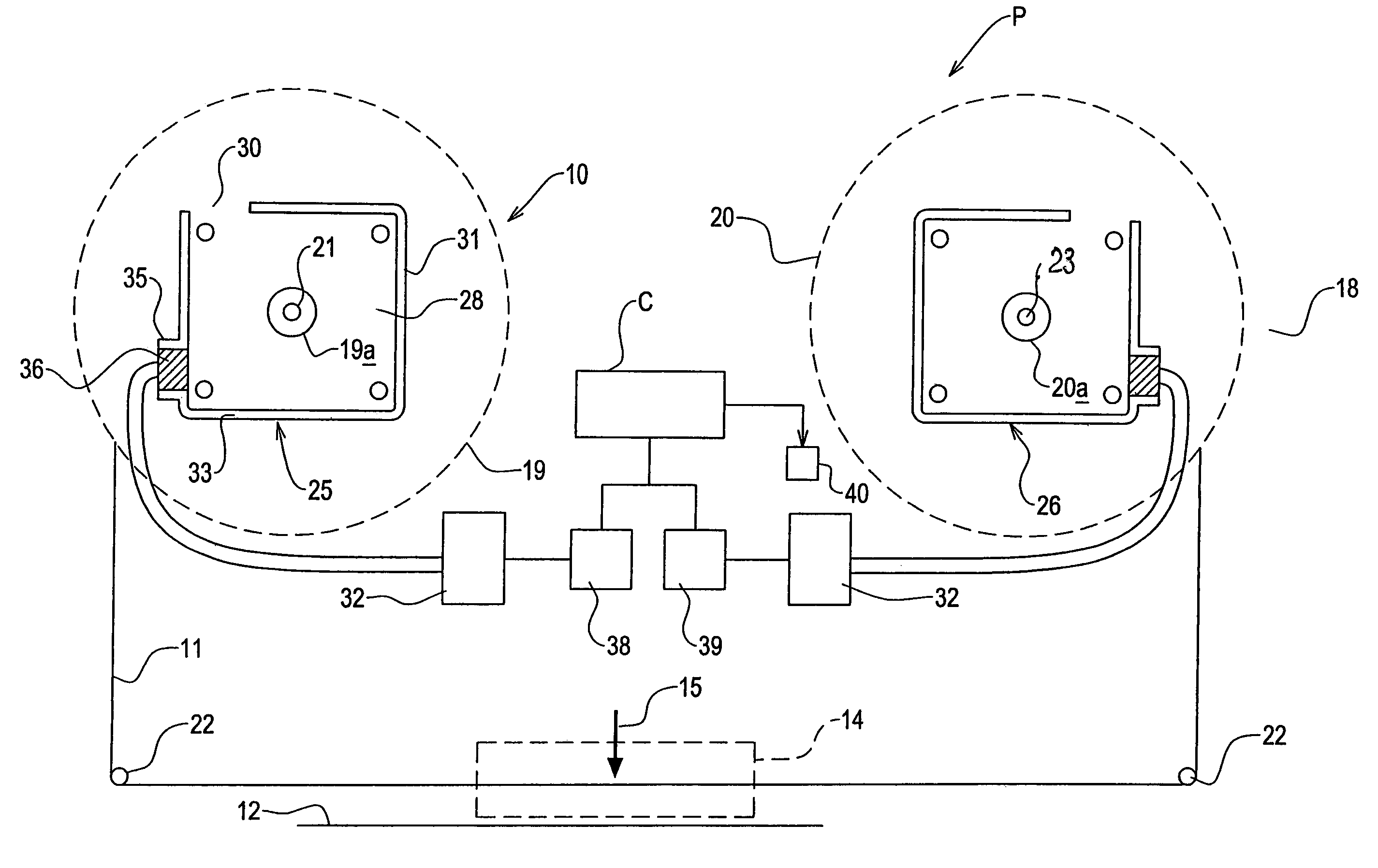
[0033]Referring to FIG. 1 of the drawings, a ribbon feed system 10 is part of a printing machine P in this example. Ribbon 11 is coated with marking medium or ink, which is deposited on a substrate 12 during a printing operation, carried out at a operation station 14, where a print head 15 is provided. In this example, the print head 15 is a so called thermal print head having a plurality of heating elements arranged in a linear array which is transverse to the direction of movement of the ribbon 11 through the printing machine P. During printing, while there is relative movement between the print head 15 and the substrate 12, the heating elements are selectively energised, to melt and thus remove pixels of marking medium from the ribbon 11, which pixels are deposited on the substrate 12. The ribbon 11 may be stationary during printing with the print head 15 moving along the ribbon 11 and substrate 12, or vice versa, or the ribbon 11 and substrate 12, and the print head 15 may all b...


PUM


Abstract

An apparatus for controlling a ribbon transport mechanism of a ribbon feed system includes a supporting structure carrying a plurality of ribbon transport devices including a ribbon storage spool, a ribbon take-up spool, and at least one ribbon guide around which roller the ribbon is passed, a ribbon feed path including the ribbon guide, between the storage and take-up spools and through an operating station where a work operation is carried out which utilises the ribbon, the ribbon transport mechanism in use, transporting the ribbon along the ribbon feed path between the storage and take-up spools, the apparatus including a mounting structure for mounting at least one of the ribbon transport devices so as to permit the respective device to move relative to the supporting structure in response to changes in ribbon tension occurring in the ribbon feed path, and a sensor device which is sensitive to such movements to provide an input which is dependant upon the extent of such spool movement, to a controller, the controller controlling operation of the transport mechanism in response.

Description

CLAIM OF PRIORITY[0001]This application claims the benefit of foreign priority under 35 U.S.C. § 119 to applications filed in Great Britain, serial number 0309039.6, filed Apr. 22, 2003, and serial number 0326656.6. filed Nov. 17, 2003, the entire contents of which are hereby incorporated by reference.BACKGROUND TO THE INVENTION[0002]This invention relates to an apparatus for controlling a ribbon transport mechanism of a ribbon feed system, such as for example only, in a printer. Such a printer typically includes a ribbon storage spool for storing ribbon, and a ribbon take-up spool for taking up used ribbon, a ribbon path between the storage and take-up spools though an operating station where a print head is provided. In use the print head may move relative to the stationary ribbon, or the ribbon may move relative to the stationary or moving print head, whilst the print head is actuated to remove marking medium from the ribbon and to deposit the marking medium on to a substrate.[00...

Claims


Application Information

Patent Timeline
Patent Type & Authority Patents(United States)
IPC IPC(8): B41J33/14B41J35/04B41J17/36B41J25/34
CPCB41J25/34B41J17/36
Inventor MILLS, PAUL
Owner MARKEM IMAJE LTD
Why Eureka
Try Eureka