Vacuum Brake Servo for a Motor Vehicle Braking System

Active Publication Date: 2012-09-13
LUCAS AUTOMOTIVE GMBH
View PDF16 Cites 0 Cited by
  • Summary
  • Abstract
  • Description
  • Claims
  • Application Information

AI Technical Summary

Benefits of technology

[0009]It is a feature of the present invention to provide a vacuum brake booster of the kind described in the introduction, in which an effective reduction of the inflow noises can be achieved with simple and inexpensive means.
[0011]The inventors have discovered that the inflow noises in a vacuum brake booster can be reduced simply by giving the guiding channel over a predetermined length a constant flow diameter which is less than the effective flow diameter of the downstream sealing seat between the surrounding atmosphere and the working chamber. In this way, a calming of the air flow which arises upon activation of the vacuum brake booster can be achieved in the guiding channel. As a result, the noises, mentioned in the introduction in a frequency range of 2.4 kHz to 8 kHz which are felt to be disturbing, are damped or displaced to a different frequency range in which they are less disturbing or no longer audible at all to human hearing.
[0013]Alternatively to this, it may also be provided that the guiding channel is formed by a separate component. For instance, according to the invention it is also possible for the guiding channel to be formed at least partly by a guiding channel sleeve, which is mounted in the control valve housing, preferably via the clamping sleeve. It is thereby possible to continue to use conventional components of a vacuum brake booster already produced and, for the reduction of the flow diameter according to the present invention, to fit an additional component which nevertheless is of relatively simple construction and therefore inexpensive to produce. The guiding channel sleeve may be made of hard dimensionally stable plastic material. Furthermore, according to one aspect of the invention it is possible for the guiding channel sleeve to have a radial projection, by which it is mounted in the control valve housing, preferably on a diameter step of the clamping sleeve. The guiding channel sleeve can be fitted on the clamping sleeve by this radial projection, for example once again by using a spring which is provided anyway. Such a spring may, for example, be the return spring for the force input member or a biasing spring provided for biasing the valve element on the sealing seat.
[0015]A development of one feature the invention provides for stepwise reduction of the flow cross-section. In this connection, it may be provided that the guiding channel is of stepped form with flow channel sections of different flow diameters, and narrows in the direction towards the valve seat, the flow channel section with the smallest flow diameter being less than or equal to the sealing seat diameter. Preferably, in this case it is provided that the guiding channel is of rounded form in the region of flow diameter steps, in order to achieve smooth transitions between the sections of different diameter.
[0016]A further contribution to the calming of the flow may also be provided by the guiding channel being of smoothly rounded form in its inlet region facing the surrounding atmosphere. This results in a low-turbulence inflow of the surrounding air, sucked in by the working chamber upon the opening of the valve seat, into the guiding channel, thus promoting the laminarity of the flow and hence the flow calming.

Problems solved by technology

These include, for example, the intake noise of a vacuum brake booster, which occurs when the brake booster is actuated from its rest position.
All the solutions from the prior art provide additional parts with relatively complicated geometry which increase the production costs of such brake boosters undesirably.
Moreover, durability problems may arise when using foam parts.

Method used


Image

  • Vacuum Brake Servo for a Motor Vehicle Braking System
  • Vacuum Brake Servo for a Motor Vehicle Braking System
  • Vacuum Brake Servo for a Motor Vehicle Braking System

Examples


Embodiment Construction

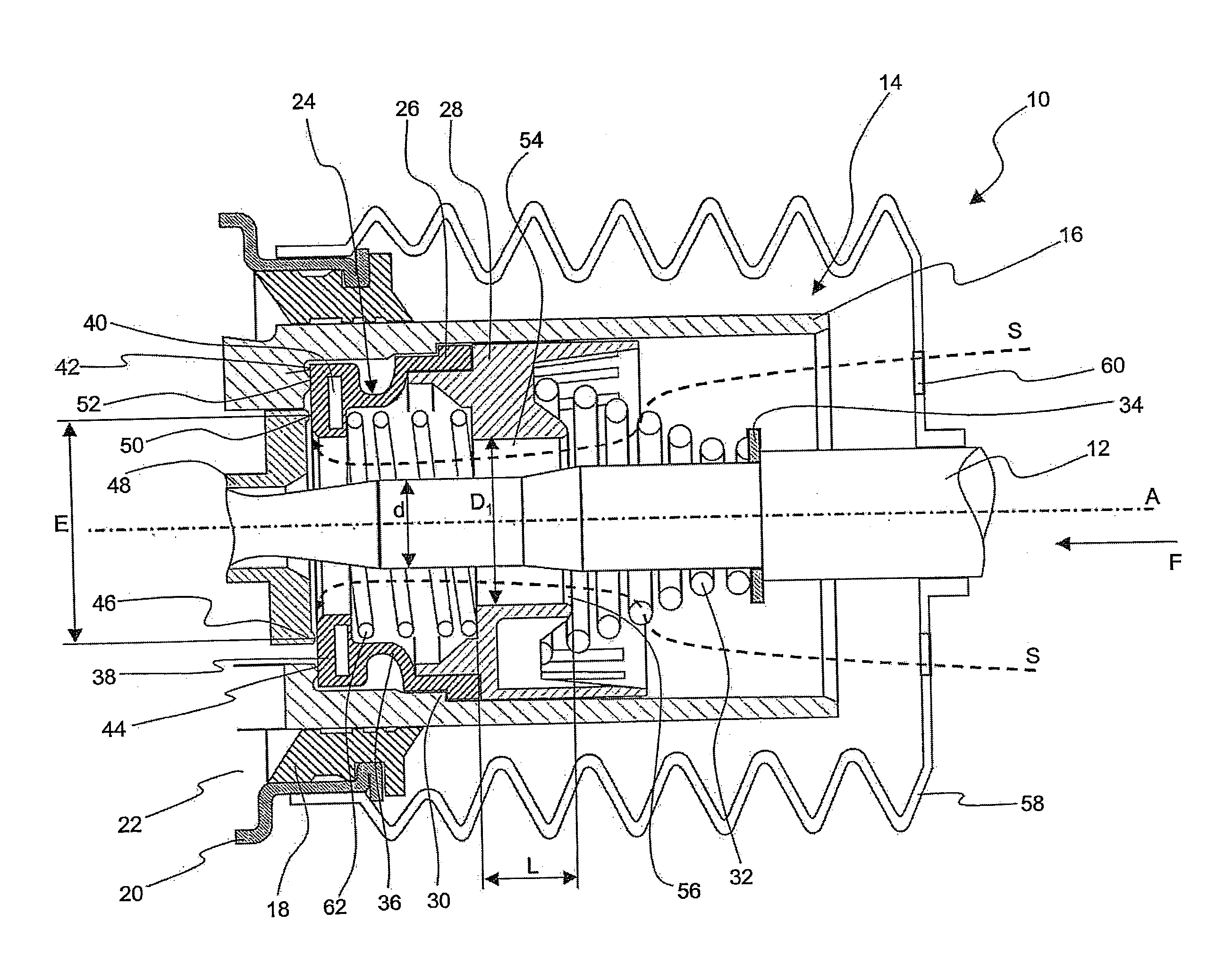
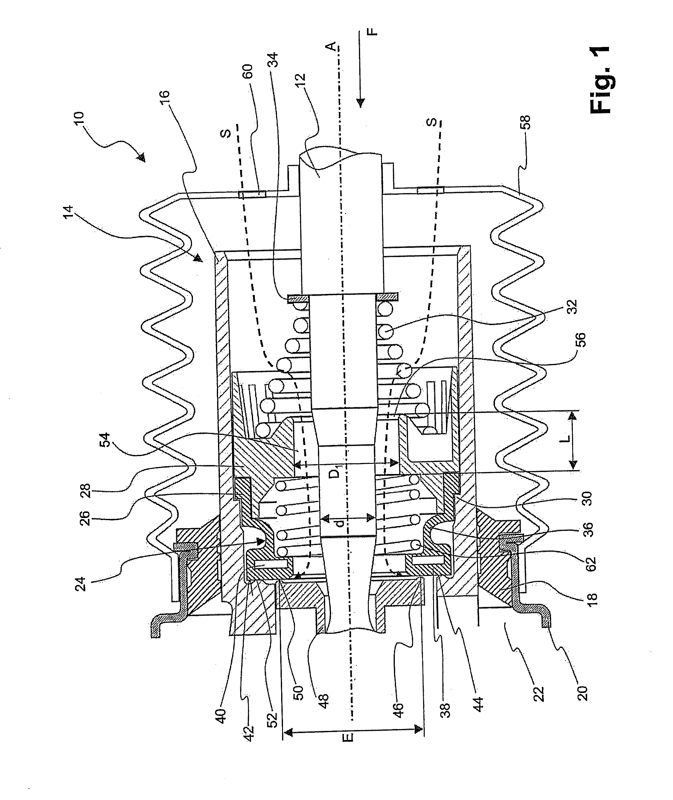
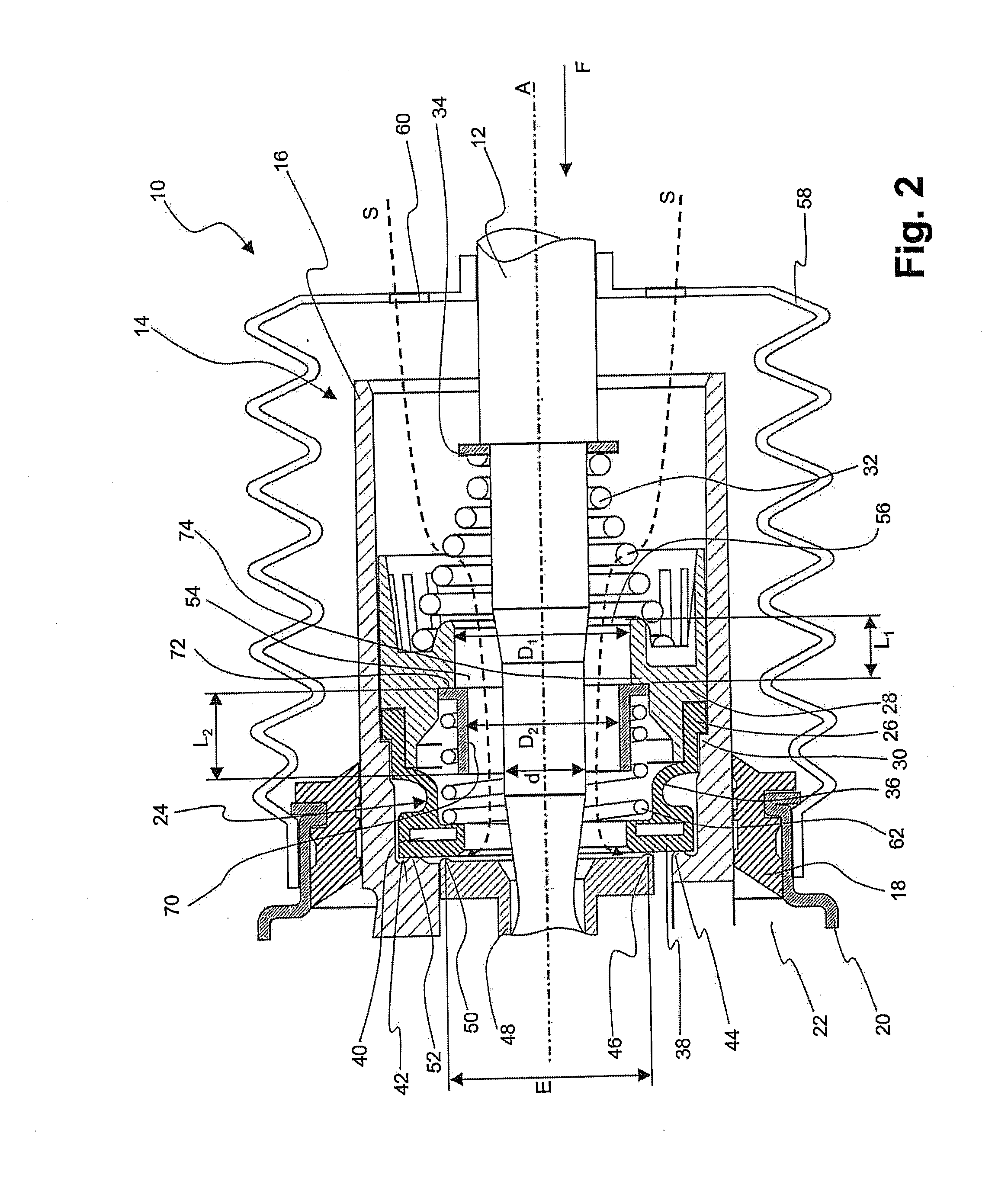
[0024]FIG. 1 shows a detail of a vacuum brake booster according to the invention in an axis-containing longitudinal sectional view, and designated generally by 10. This vacuum brake booster comprises a force input member 12, which at its right-hand end in FIG. 1 faces a connection mechanism, by which it is coupled or can be coupled with a brake pedal. At its left-hand end in FIG. 1, the force input member 12 faces in the direction of a brake master cylinder arrangement (not shown). A control valve 14 is arranged in the vacuum brake booster 10 around the force input member 12. This control valve comprises a control valve housing 16, which is displaceably guided in a brake booster housing 20 in a sealing manner via a seal 18. Arranged in this brake booster housing 20 is a chamber arrangement, which has, in a manner known per se, a working chamber 22 and a vacuum chamber (not shown), the working chamber and the vacuum chamber being separated from one another via a moveable wall (not sh...


PUM


Abstract

The invention relates to a vacuum brake servo for a motor vehicle braking system, comprising a rod-like force input element which is coupled or can be coupled to a brake pedal, a control valve which is actuated by means of the force input element, a chamber arrangement having a vacuum chamber which can be connected to a vacuum source, and also having an operating chamber which, depending on the actuation of the force input element, can optionally be connected to the vacuum chamber and to the surrounding atmosphere. The control valve has a control piston that can be actuated by means of the force input element and, together with a valve element, forms a seal seat having a seal seat diameter between the operating chamber and the surrounding atmosphere. In the area close to the seal seat, a guide channel is provided, through which, when the seal seat is opened, air from the surrounding atmosphere flows into the operating chamber as a result of a pressure difference. In order to reduce the intake noise, provision is made in the guide channel for the latter to extend in the axial direction with a constant flow diameter over a predetermined length, wherein the flow diameter is less than or equal to the seal seat diameter.

Description

CROSS-REFERENCE TO RELATED APPLICATIONS[0001]This application is a national stage of International Application No. PCT / EP2010 / 006447 filed Oct. 21, 2010, the disclosures of which are incorporated herein by reference, and which claimed priority to German Patent Application No. 10 2009 051 236.5 filed Oct. 29, 2009, the disclosures of which are incorporated herein by reference.BACKGROUND OF THE INVENTION[0002]The present invention relates to a vacuum brake booster for a motor vehicle brake system comprising a rod-like force input member, which is coupled or can be coupled with a brake pedal, a control valve, which can be actuated by means of the force input member, a chamber arrangement having a vacuum chamber, which is connectable to a vacuum source, as well as a working chamber, which is, in accordance with the actuation of the force input member, selectively connectable to the vacuum chamber and to the surrounding atmosphere, wherein the control valve has a control piston actuatabl...

Claims


Application Information

Patent Timeline
IPC IPC(8): F15B13/04
CPCB60T13/57
Inventor CALVO MARTINEZ, JOSE MANUELSPARFELD, JENSKNIGGE, DETLEVZINNKANN, ULRICH
Owner LUCAS AUTOMOTIVE GMBH
Why Eureka
Try Eureka