Motor-vehicle braking system having a vacuum-operated assistance device

a technology of assistance device and motor vehicle, which is applied in the direction of braking system, machine/engine, transportation and packaging, etc., can solve the problems of implying the use of relatively expensive and/or relatively bulky devices

Active Publication Date: 2022-07-19
FCA ITAL
View PDF14 Cites 0 Cited by
  • Summary
  • Abstract
  • Description
  • Claims
  • Application Information

AI Technical Summary

Benefits of technology

[0006]The object of the present invention is that of reducing the waste of energy due to the vacuum pump being driven by the internal combustion engine, with the aid of extremely simple and inexpensive means.SUMMARY OF THE INVENTION
[0014]Due to the above-indicated features, when the pressure in the chamber of the assistance device is lower than said threshold value, which means that in said chamber there is a vacuum sufficient for the regular operation of the braking system, the inlet side of the vacuum pump is in communication with the atmosphere. Therefore, in this condition the vacuum pump intakes air from the atmosphere and feeds air into the atmosphere (the outlet side of the vacuum pump is always in communication with the atmosphere). This condition corresponds to a minimum energy level which must be spent by the internal combustion engine in order to drive the vacuum pump. Therefore, in this manner, by the simple addition of one valve, having a reduced bulk and a relatively low cost, the problem is solved to avoid a useless energy waste in the conditions in which the action of the pump is not required. Therefore, this goal is achieved with no need of providing a friction clutch between the pump and the internal combustion engine or an electronically controlled electric motor for actuating the pump, as it is instead the case in the known solutions which have been mentioned above.

Problems solved by technology

Both the above-indicated known solutions have the drawback of implying the use of relatively costly and / or relatively bulky devices.

Method used


Image

  • Motor-vehicle braking system having a vacuum-operated assistance device
  • Motor-vehicle braking system having a vacuum-operated assistance device
  • Motor-vehicle braking system having a vacuum-operated assistance device

Examples


Embodiment Construction

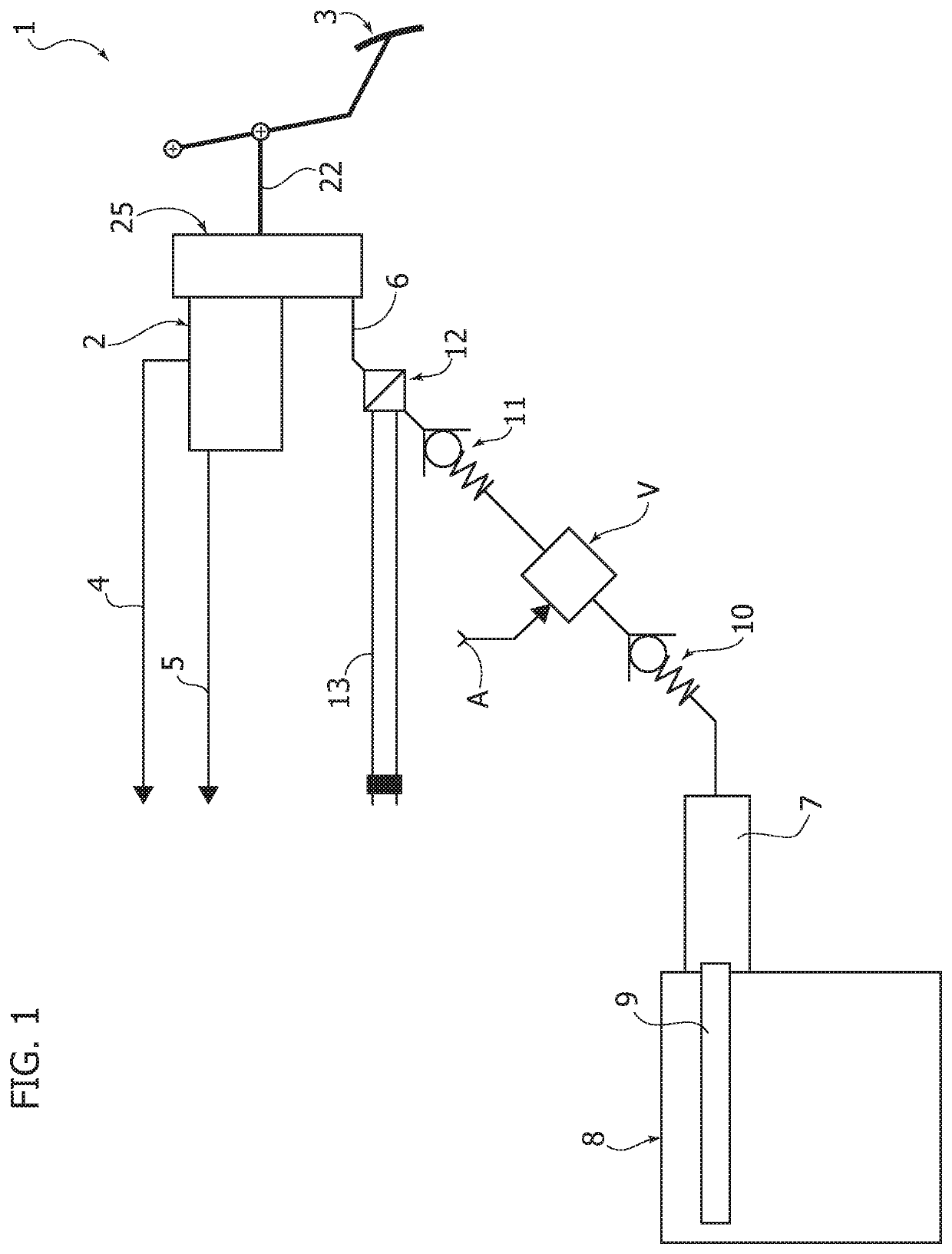
[0023]In FIG. 1, reference numeral 1 generally designates a motor-vehicle braking system comprising a master cylinder 2 which is actuated by a brake pedal 3 in order to feed pressurized hydraulic fluid to the brakes associated with the wheels of the motor-vehicle through two lines 4, 5.

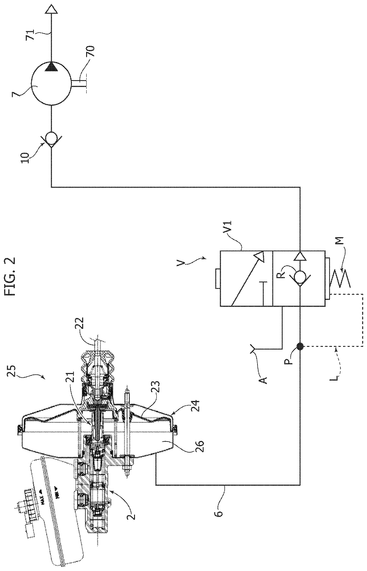
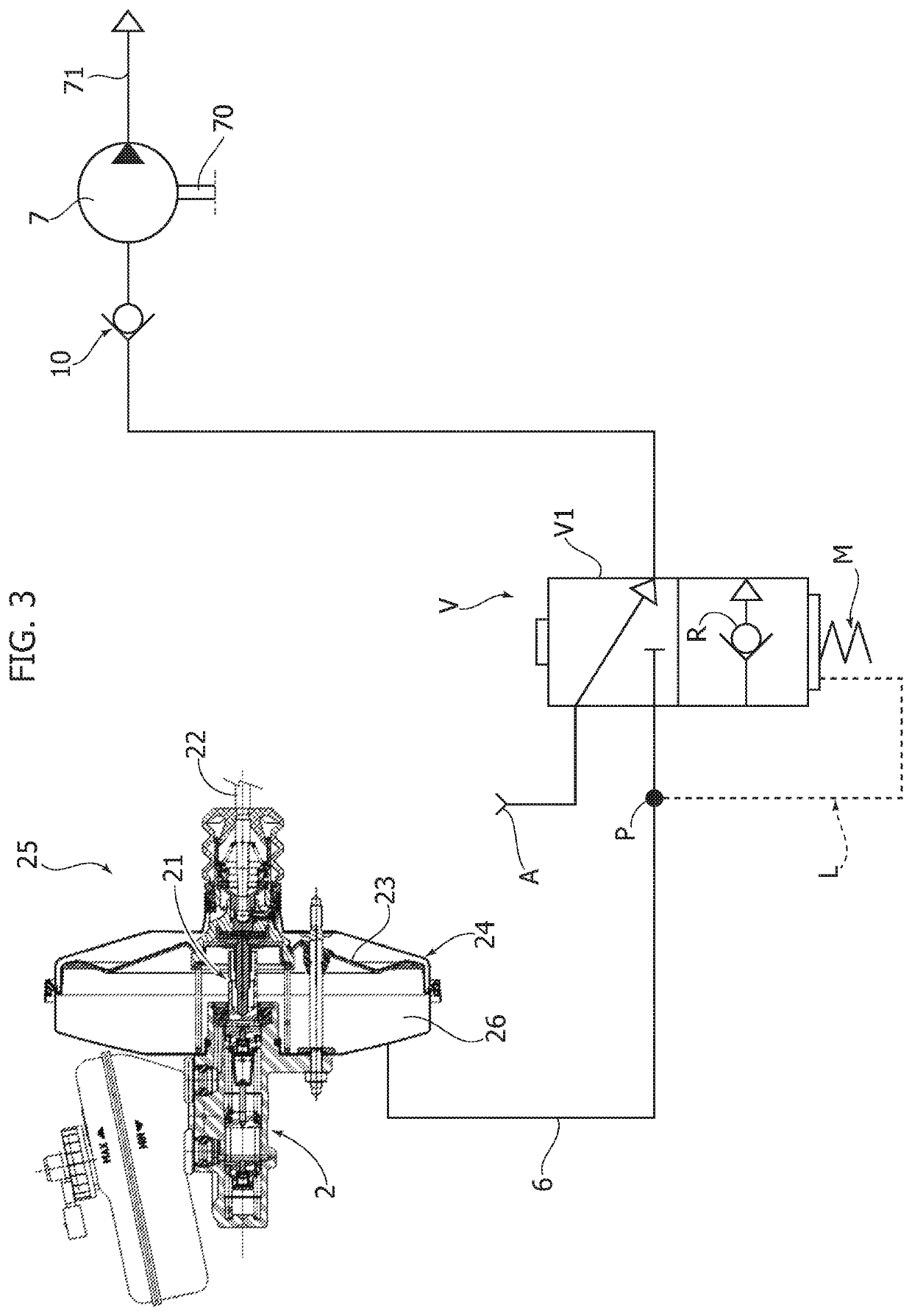
[0024]As shown in the purely exemplary representation of FIGS. 2, 3, the master cylinder 2 has an actuating stem 21 which is operatively connected both to the brake pedal 3 by means of the a rod 22, and to a diaphragm 23 arranged inside the casing 24 of an assistance device, or “booster”, 25. The diaphragm 23 is facing towards a chamber 26 of the assistance device 25 which is in communication, through a fluid communication line 6, with the inlet side of a vacuum pump 7 which, according to the conventional art, is constantly driven by the crankshaft of the internal combustion engine 8 of the motor-vehicle (see FIG. 1). In the specific example illustrated herein, the shaft 70 of the pump 7 (FIG. 2) is d...


PUM


Abstract

A vehicle braking system includes an assistance device having a vacuum pump driven by an engine for communicating vacuum to a chamber of the assistance device. A control valve is interposed along a fluid line between the pump and the chamber. The control valve is in its first operative condition, where the inlet side of the vacuum pump communicates with the chamber, when pressure within the chamber is above a predetermined value; and is in its second operative condition, where the inlet side of the vacuum pump communicates with the atmosphere, when pressure within the chamber is below a predetermined value. In this second condition the pump intakes air from and feeds air into the atmosphere, thereby reducing the energy consumption by the engine required for driving the pump during stages where, within the chamber, there is a vacuum sufficient for the regular operation of the braking system.

Description

CROSS-REFERENCE TO RELATED APPLICATION[0001]This application claims priority to European Patent Application No. 19 164 242.0 filed Mar. 21, 2019. The disclosure of the above application is incorporated herein by reference in its entirety.FIELD OF THE INVENTION[0002]The present invention relates to motor-vehicle braking systems provided with a vacuum-operated assistance device, or “booster”, comprising a vacuum pump which is to be driven by the motor-vehicle engine, a fluid communication line between the vacuum pump and a chamber of said assistance device, for communicating a vacuum generated by said vacuum pump to said chamber, and at least one one-way valve interposed in said fluid communication line for enabling a flow of air only in the direction which goes from said chamber of the assistance device towards the vacuum pump.PRIOR ART[0003]A system of the above-indicated type is for example described and shown in document US 2014 / 0171264 A1. In the solution shown in this document, ...

Claims


Application Information

Patent Timeline
Patent Type & Authority Patents(United States)
IPC IPC(8): B60T13/57B60T13/24B60T13/72B60T17/02B60T17/22
CPCB60T13/57B60T13/246B60T13/72B60T17/02B60T17/22B60T2220/04F02D2250/41B60T13/52
Inventor MARCOLONGO, GIANLUCABADINO, RENATOIELUZZI, MICHELEGABIATI, GIOVANNILUCÀ, STEFANOGRAZIANO, PAOLO
Owner FCA ITAL
Why Eureka
Try Eureka