Method and apparatus for echolocation

a technology of echolocation and echolocation, applied in the direction of instruments, measurement devices, and using reradiation, can solve the problems of bats not being able to distinguish individual objects with so wide a beam, and receiving echoes from ahead of the transducer, and achieve the effect of accurate determination of the sound intensity vector

Inactive Publication Date: 2006-05-30
HICKLING ROBERT
View PDF4 Cites 11 Cited by
  • Summary
  • Abstract
  • Description
  • Claims
  • Application Information

AI Technical Summary

Benefits of technology

[0036](f) determines additional information from the Doppler shift of the echo highlights.
[0037]The present invention includes and utilizes an echolocation system for robot guidance and assisting the blind. It is modeled on the echolocation abilities of bats. It combines into one instrument a source of pulsed ultrasound and a recently developed acoustic vector probe (AVP). This instrument is used in conjunction with a data acquisition system, a signal processor and an output device. The source emits pulses of ultrasound over a beam width of about 100 degrees and the AVP detects backscattered pulses from a discrete distribution of acoustic highlights on surrounding objects. The ultrasonic sound pressures of the backscattered pulses is measured at each of the four microphones of the AVP, which are then heterodyned in the digital signal processor d

Problems solved by technology

However measurement with an AVP is presently limited to the audible frequency range below about 15 kHz, because the measurement calculations for the AVP are based on finite-difference approximations that are valid only when the wavelength of sound exceeds the spacing d between microp

Method used


Image

  • Method and apparatus for echolocation
  • Method and apparatus for echolocation
  • Method and apparatus for echolocation

Examples


Embodiment Construction

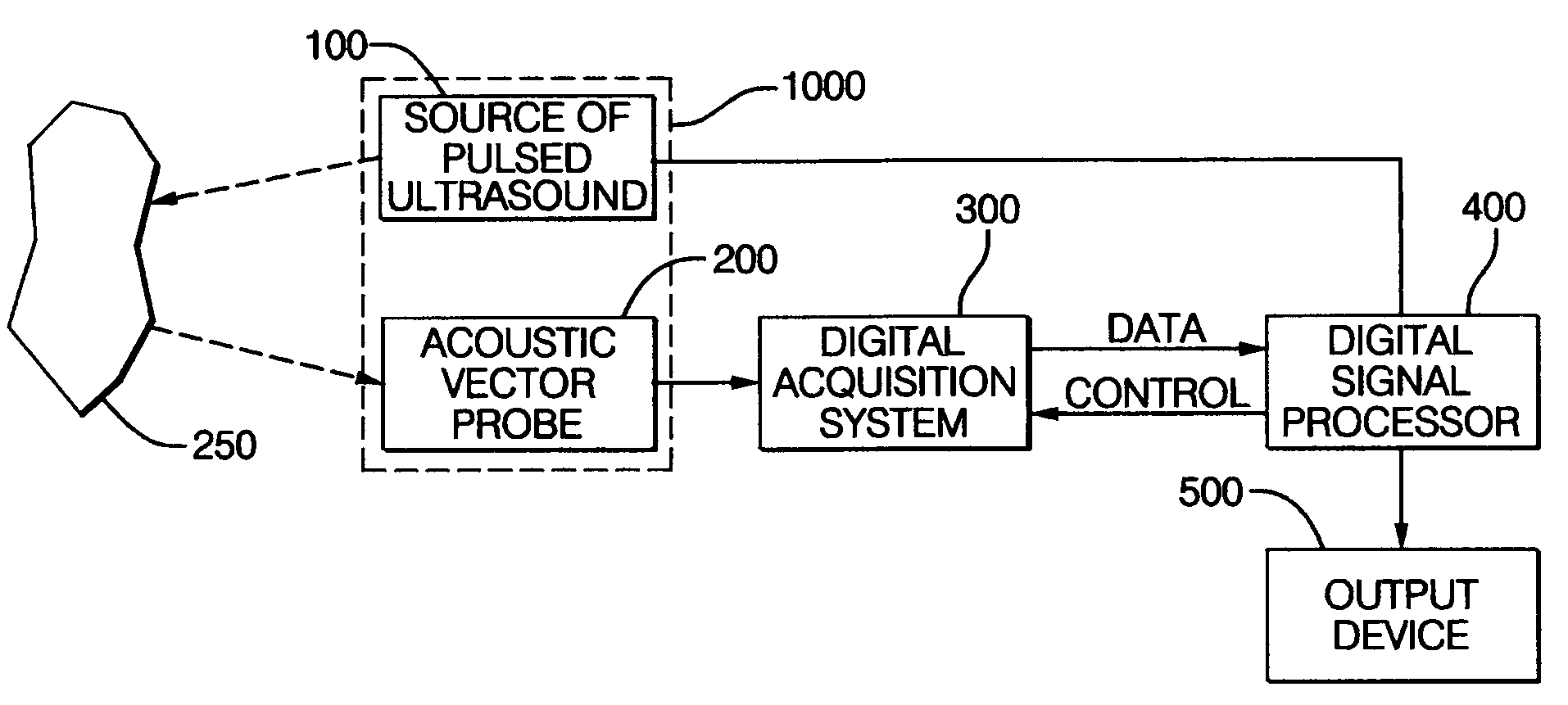
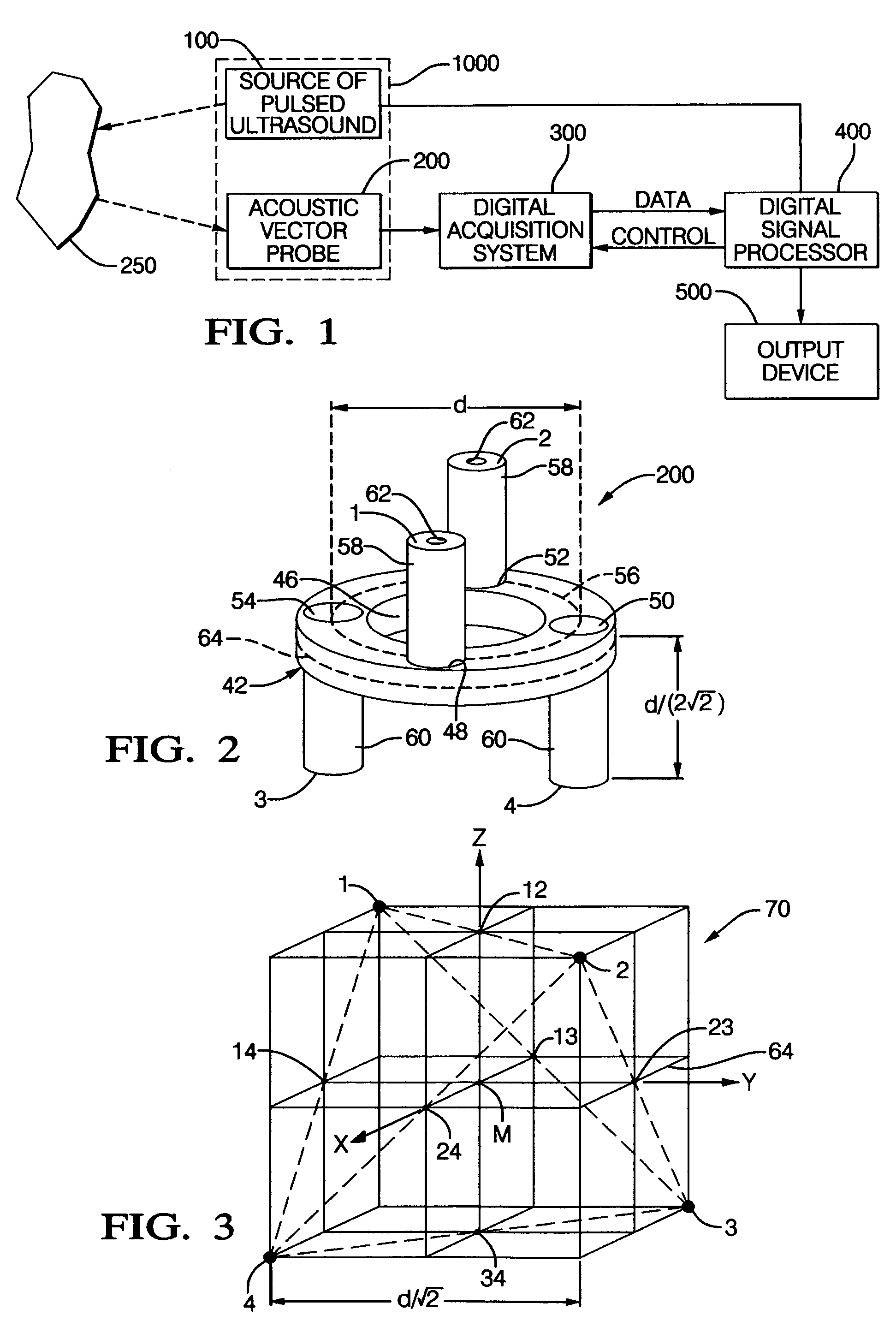
[0044]FIG. 1 is a block diagram showing the different components of the invention. A source of pulsed ultrasound 100 is combined with an acoustic vector probe (AVP) 200 to form an echolocation instrument 1000 linked to a data acquisition system 300, a digital signal processor 400 and a display unit 500. The processor controls the source 100 and the data acquisition system 300. Backscattered echoes to the pulses from the source 100 are returned by an object 250 to the probe 200.

[0045]FIGS. 2 and 3 illustrate the structure and function of the AVP 200 in determining the sound-intensity vector. AVP 200 includes a fixture 42 being an annular member formed as a ring with a central opening 46. Protruding from the ring are four support tubes for the microphones parallel to the axis of the ring, two on one side of the ring pointing in one direction and two on the reverse side pointing in the opposite direction. These tubes are spaced around the ring at ninety degree intervals at openings in ...


PUM


Abstract

Method and apparatus for application of echolocation to robot guidance and assisting the blind. The method is based on the echolocation of bats. It combines a source of pulsed ultrasound (100) with a recently-developed acoustic vector probe (AVP) (200) into an echolocation instrument (1000), together with a data-acquisition system (300), a digital signal processor (400) and an output device (500). The source emits pulses of ultrasound of about 35 kHz over a beam angle of approximately 100 degrees and the AVP detects backscattered pulses from a discrete distribution of acoustic highlights on surrounding objects. The ultrasonic sound pressures of the backscattered pulses are heterodyned down to lower frequencies so that the signal processor can make an accurate determination of the sound-intensity vector for each pulse. The sound-intensity vector points in the direction of the highlight from which the backscattered pulse originates while the round-trip time of flight of the pulse determines the distance to the highlight. In this way the positions of the highlights on surrounding objects can be determined. The distribution of such highlights changes when the echolocation instrument moves relative to surrounding objects, generating a sequence of highlight distributions that can be stored in the memory of the processor and combined to provide a more complete representation of surrounding objects.

Description

[0001]THIS APPLICATION IS A CONTINUATION-IN-PART OF US patent application ENTITLED “ACOUSTIC MEASUREMENT METHOD AND APPARATUS” Ser. No. 10 / 396,541, FILED 2003, MAR. 25, ALSO OF CONTINUATION-IN-PART ENTITLED “METHOD AND APPARATUS FOR ACOUSTIC DETECTION OF BURIED OBJECTS” Ser. No. 10 / 658,076, FILED 2003 SEP. 9 now U.S. Pat. No. 6,862,252, AND ALSO OF CONTINUATION-IN-PART ENTITLED “SOUND SOURCE LOCATION AND QUANTIFICATION USING ARRAYS OF VECTOR PROBES” Ser. No. 10 / 746,763, FILED 2003, DEC. 26, ALL THREE SUBMITTED BY ROBERT HICKLING, THE PRESENT INVENTOR.TECHNICAL FIELD[0002]This invention relates to an echolocation instrument for robot guidance and for aiding the blind that combines a recently developed acoustic vector probe (AVP) and a source of pulsed ultrasound.BACKGROUND OF THE INVENTIONAcoustic Vector Probes[0003]Recently a patent application was filed for a new acoustic instrument, the acoustic vector probe (AVP).[0004]1. R. Hickling 2003, “Acoustic Measurement Method and Apparat...

Claims


Application Information

Patent Timeline
IPC IPC(8): G01S15/00
CPCG01S15/42
Inventor HICKLING, ROBERT
Owner HICKLING ROBERT
Why Eureka
Try Eureka