

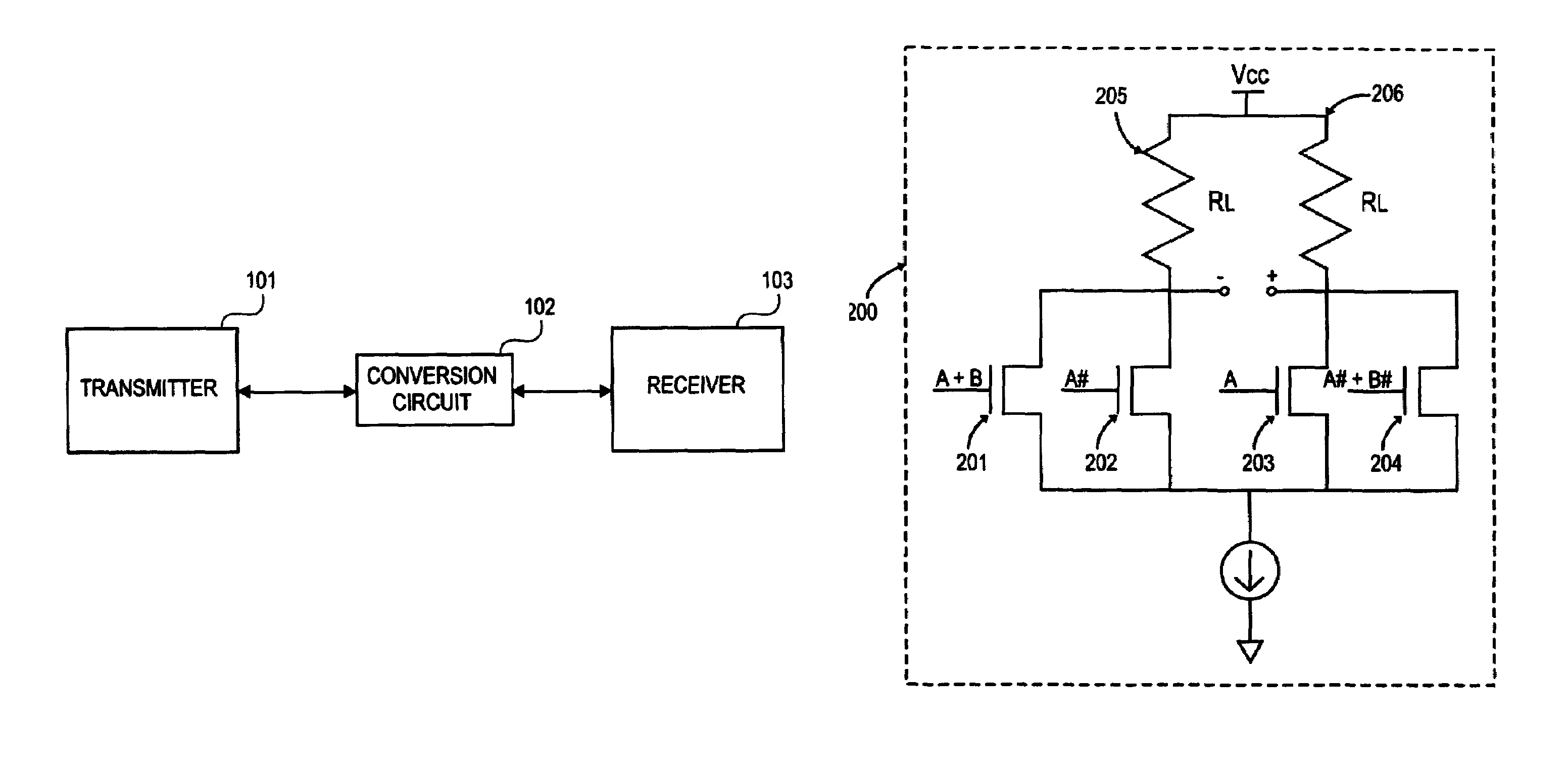
Differential simultaneous bi-directional receiver
a receiver and differential technology, applied in the direction of digital transmission, transmission, duplex signal operation, etc., can solve the problems of large noise source, increased circuit cost, and very rapid draw down of voltage rails
- Summary
- Abstract
- Description
- Claims
- Application Information
AI Technical Summary
Benefits of technology
Problems solved by technology
Method used
Image

Examples
Embodiment Construction
[0024]It is worthy to note that any reference herein to “one embodiment” or “an embodiment” means that a particular feature, structure, or characteristic described in connection with the embodiment is included in at least one embodiment of the invention. The appearances of the phrase “in one embodiment” in various places in the specification are not necessarily all referring to the same embodiment.
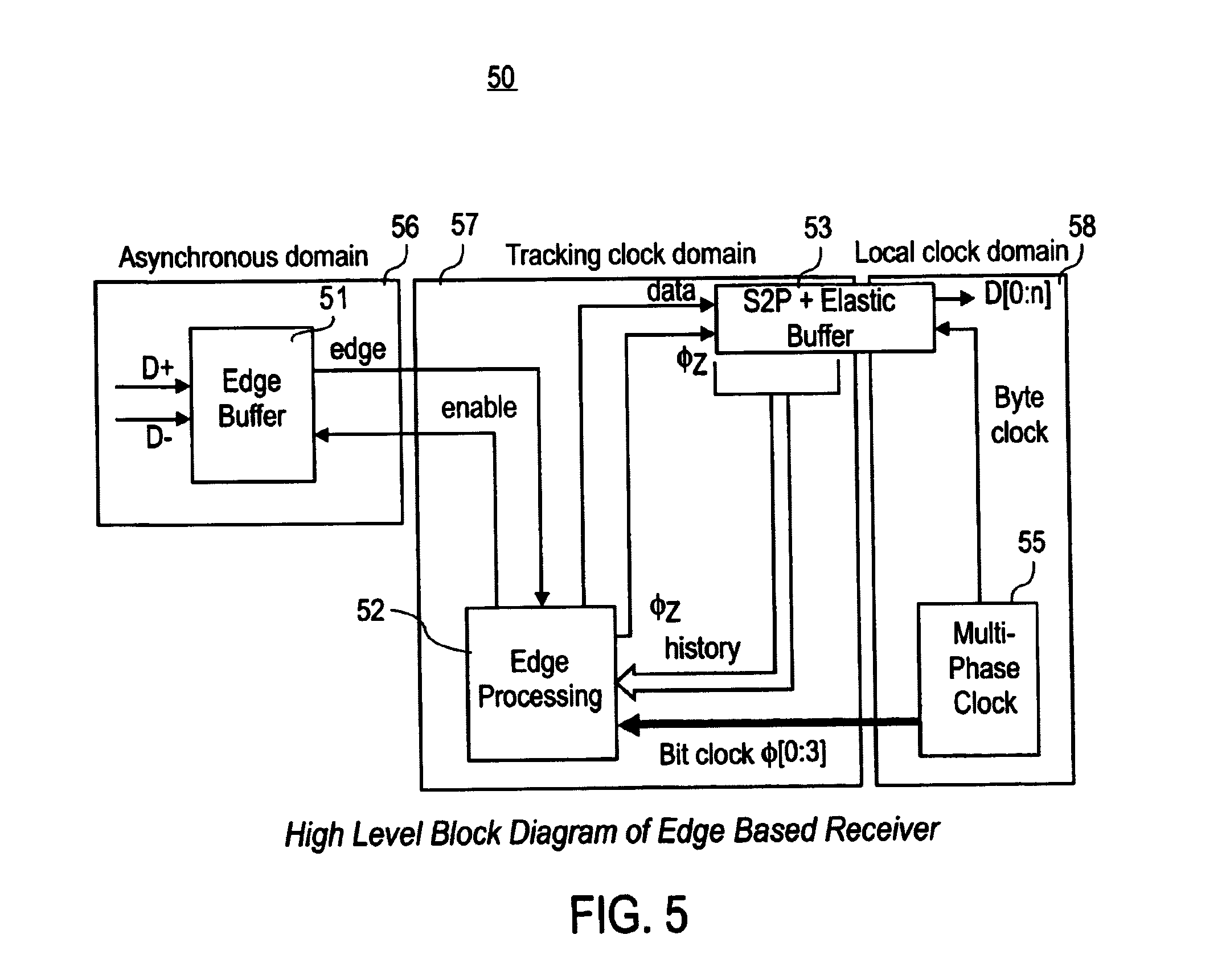
[0025]One embodiment of the invention includes an edge-based receiver to overcome the problems associated with both tracking and oversampling receivers. In an edge-based receiver, high-speed communication is accomplished without the use of analog circuitry and the concomitant noise and other limitations associated with the use of analog circuitry.
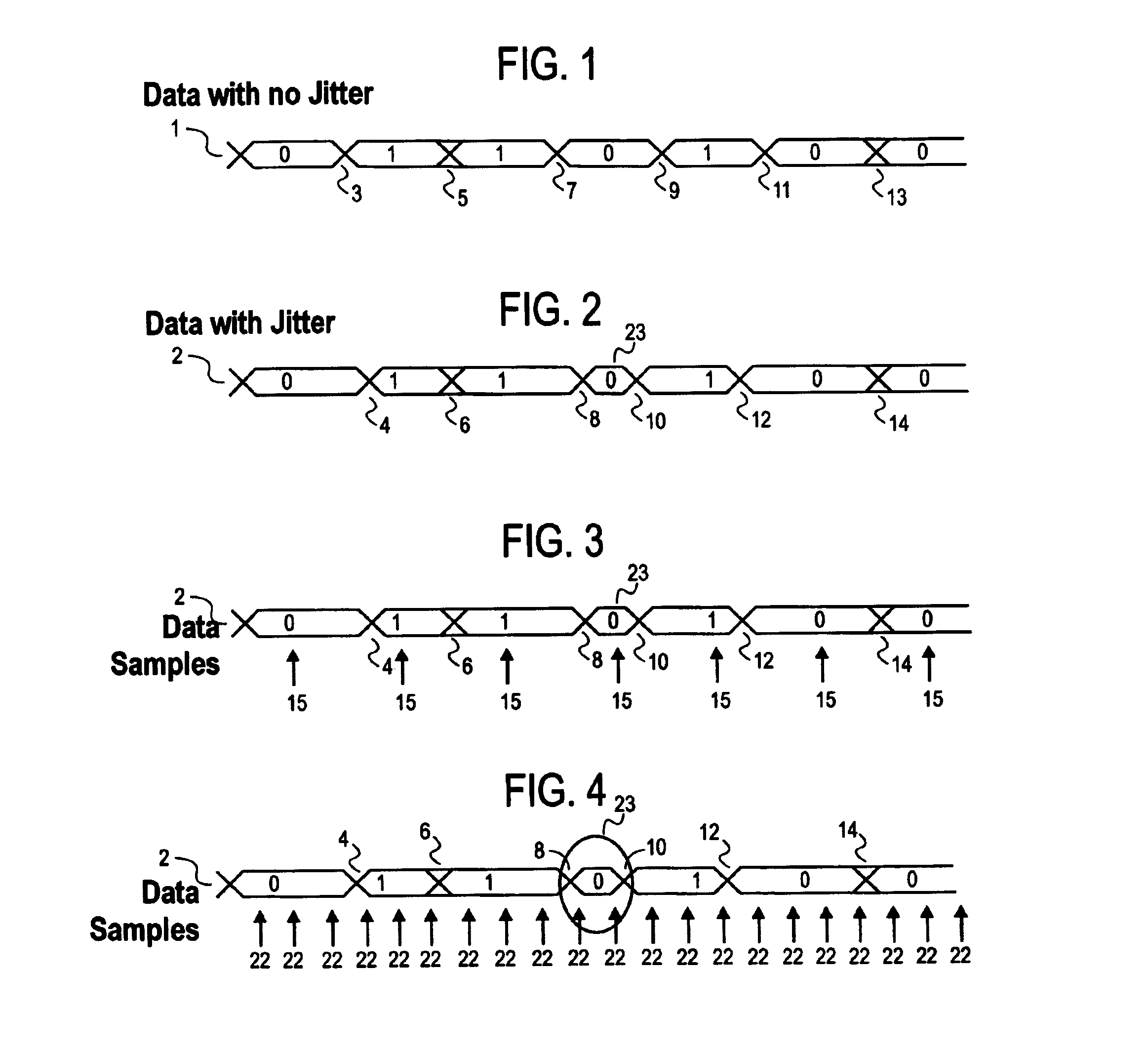
[0026]An edge based receiver bases decisions regarding received data on edges detected in a received waveform. The edge-based receiver operates by detecting “zero crossings” or edges of the input data waveform. Zero crossings are those time instan...
PUM
 Abstract
Description
Claims
Application Information