Bullet ended wash tube for dishwasher

a wash tube and washer technology, applied in the direction of washing/rinsing machines, household cleaners, tableware washing/rinsing machines, etc., can solve the problems of inefficient water flow from the manifold into the wash tube, and the water in the wash tube is not at optimal pressure, so as to increase the tolerance of docking or coupling, reduce velocity, and increase pressure

Active Publication Date: 2006-06-06
MAYTAG
View PDF14 Cites 47 Cited by
  • Summary
  • Abstract
  • Description
  • Claims
  • Application Information

AI Technical Summary

Benefits of technology

[0011]An improved wash tube is provided for a dishwasher having a wash chamber and a rack movable between an extended loading position substantially out of the wash chamber and a retracted cleaning position within the wash chamber. The dishwasher has a water manifold in a rear wall of the wash chamber. The wash tube is mounted to the rack, and extends between the water manifold and a rotatable spray arm for spraying water onto objects to be cleaned. The tube has an elongated body with a first end adapted to releasably dock with the water manifold, and a second end adapted to be mounted to the spray arm. The first end has a bullet-shape so as to provide increased tolerances for the docking or coupling of the wash tube with the water manifold. The bullet end includes a downwardly oriented opening so as to define a cup which directs water from the manifold into the wash tube at a reduced velocity and increased pressure. The bullet ended wash tube may engage the rear wall of the water manifold without obstructing the inlet opening which is oriented in a plane perpendicular to the flow of water through the manifold.

Problems solved by technology

The docking of the wash tube with the water manifold presents several problems in the prior art.
Secondly, the flat end of the wash tube defines an opening or inlet which is in a plane parallel to the water flow in the water manifold. Thus, the flow of water from the manifold into the wash tube is not efficient. Also, the water in the wash tube is not at optimal pressure.

Method used


Image

  • Bullet ended wash tube for dishwasher
  • Bullet ended wash tube for dishwasher
  • Bullet ended wash tube for dishwasher

Examples


Embodiment Construction

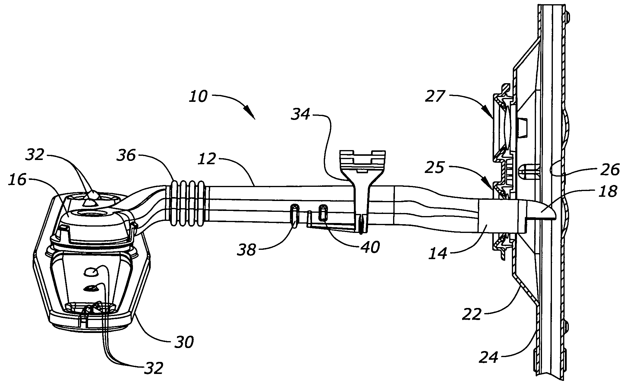
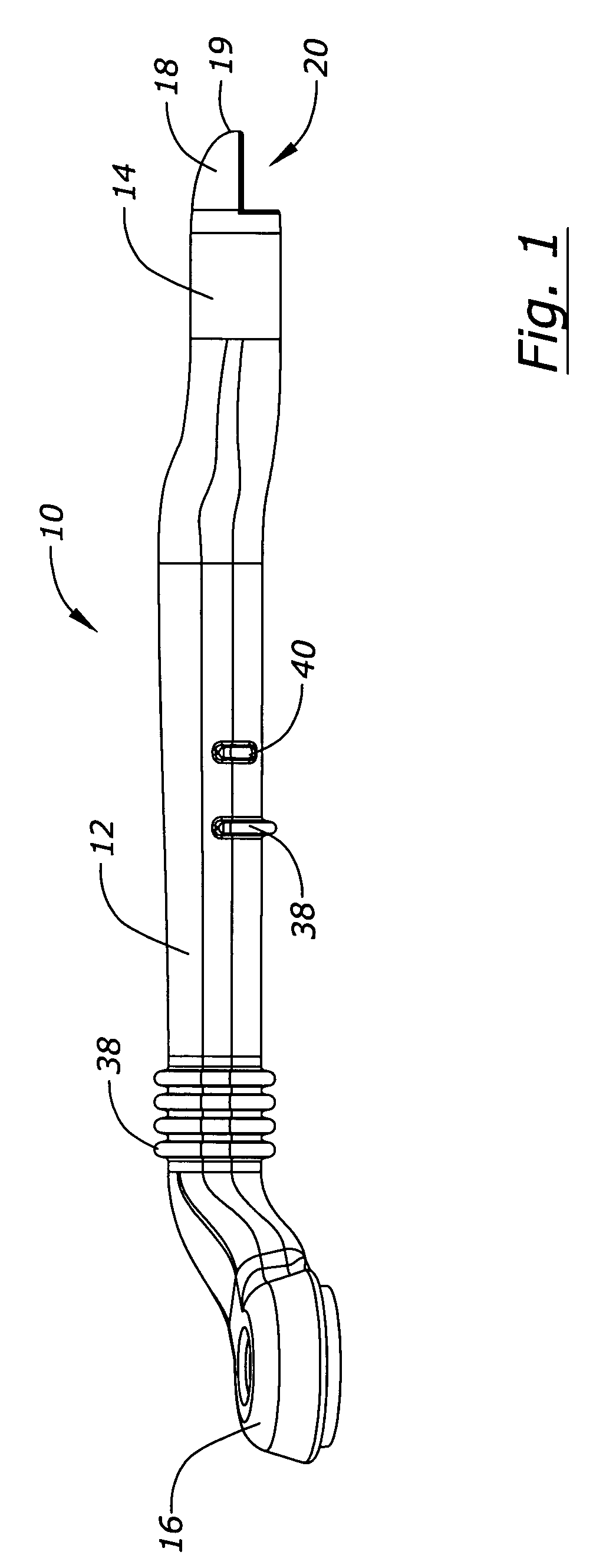
[0016]The improved wash tube of the present invention is generally designated in the drawings by the reference numeral 10. The wash tube 10 has a body 12 with opposite first and second ends 14, 16, respectively.

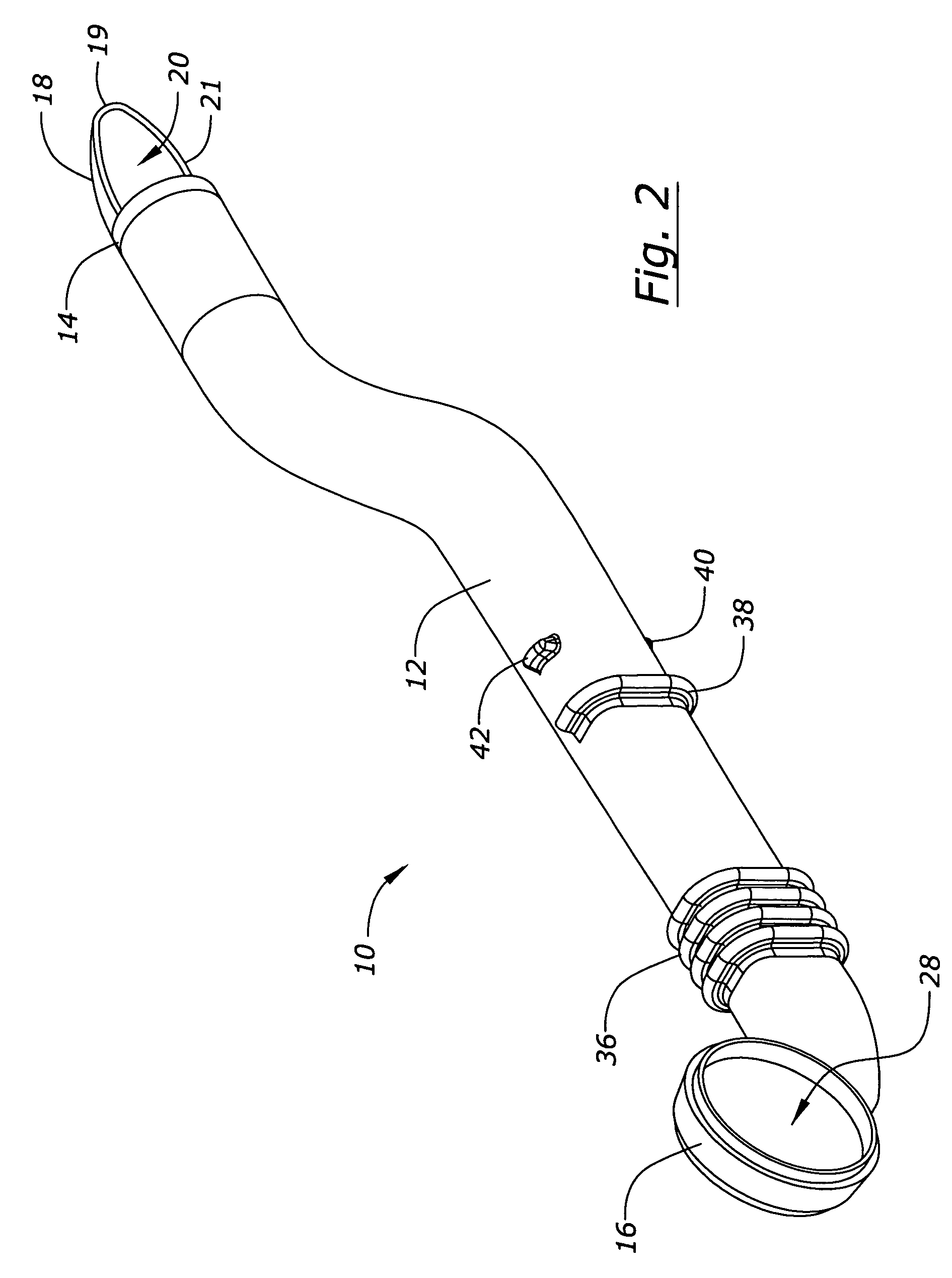
[0017]The first end 14 of the wash tube 10 terminates in a curved, bullet shaped cap 18, as best seen in FIG. 1. The cap 18 extends from the upper ½ of the tube end 14, with a semi-circular connection to the tube end 14 and tapering to a narrowed, rounded nose 19. The cap has a horizontally disposed, U-shaped lower perimeter edge 21, seen in FIG. 2, defining a water inlet 20, which is oriented in a horizontal plane, as best seen in FIG. 1. The first end 14 is adapted to be coupled to a docking station 22 in a water manifold 24 located in the rear wall of the washing chamber of the dishwasher. The cap 18 captures water flowing upwardly through the manifold 24 and redirects the flow of water approximately 90° from the vertically upward flow through the water manifold 24 to a ho...


PUM


Abstract

An improved wash tube is provided for a dishwasher. The wash tube is mounted on the upper rack and has a first end adapted to be releasably docked with the water manifold in the back of the dishwashing chamber as the rack is moved between the extended loading position and the retracted wash position. The inner end of the wash tube includes a curved cap which increases the docking tolerance and which presents a substantially downwardly oriented water inlet to the wash tube. The cap creates water stagnation adjacent the inlet such that the water velocity is substantially reduced and the pressure increased. The second end of the wash tube is connected to the spray arm which rotates as water is ejected from the spray arm nozzles at increased pressure. The cap allows the wash tube to fully dock into the manifold without obstructing the water inlet.

Description

BACKGROUND OF THE INVENTION[0001]Dishwashers typically have upper and lower racks for holding objects to be washed. Rotatable spray arms are provided in the chamber for spraying water onto the objects for cleaning. Often times, one of the spray arms is positioned between the upper and lower racks, with a wash tube extending between the spray arm and the water manifold in the back wall of the washing chamber. The wash tube is connected to the upper rack and is adapted to dock to and undock from the water manifold, such that the wash tube and spray arm move with the rack between the extended loading position substantially outside of the wash chamber and the retracted wash position within the wash chamber.[0002]The docking of the wash tube with the water manifold presents several problems in the prior art. First, the wash tube must be aligned with the manifold opening to allow for proper docking. While a tapered end on the wash tube has somewhat reduced the docking alignment problem, t...

Claims


Application Information

Patent Timeline
Patent Type & Authority Patents(United States)
IPC IPC(8): B08B3/00A47L15/22A47L15/50
CPCA47L15/508A47L15/22
Inventor ELICK, ROBERT A.MORRISON, JOHN TREVOR
Owner MAYTAG
Why Eureka
Try Eureka