
Non-contacting clearance seal for high misalignment applications

a clearance seal and high misalignment technology, applied in the direction of engine seals, shafts and bearings, bearing components, etc., can solve the problems of leakage in high misalignment applications, and achieve the effect of eliminating oil leakage and reducing negative pumping action

Inactive Publication Date: 2006-06-06
HONEYWELL INT INC
View PDF38 Cites 9 Cited by
  • Summary
  • Abstract
  • Description
  • Claims
  • Application Information

AI Technical Summary

Benefits of technology

[0009]In accordance with the invention, an improved slinger rotor for an improved oil seal is provided for reducing negative pumping action caused by the opening and closing of the gap between the seal rotor and housing as the shaft rotates through 360□ in high misalignment applications. The invention is particularly suited for use in association with dynamic air-oil separator structures of an oil seal for substantially eliminating oil leakage along a possibly misaligned rotatable shaft extending through a shaft passage formed in an end wall of a bearing housing in a turbomachine or the like, including, for example, ATS applications with ratchet & pawl clutch assemblies. The invention may also be used with other types of clutch assemblies, e.g., sprag clutch assemblies, and flyweight actuated clutch assemblies such as described in U.S. Pat. No. 5,419,420, incorporated herein by reference. The improved rotor and oil seal includes a slinger rotor mounted within the bearing housing, at the inboard side of the end wall of the bearing housing.
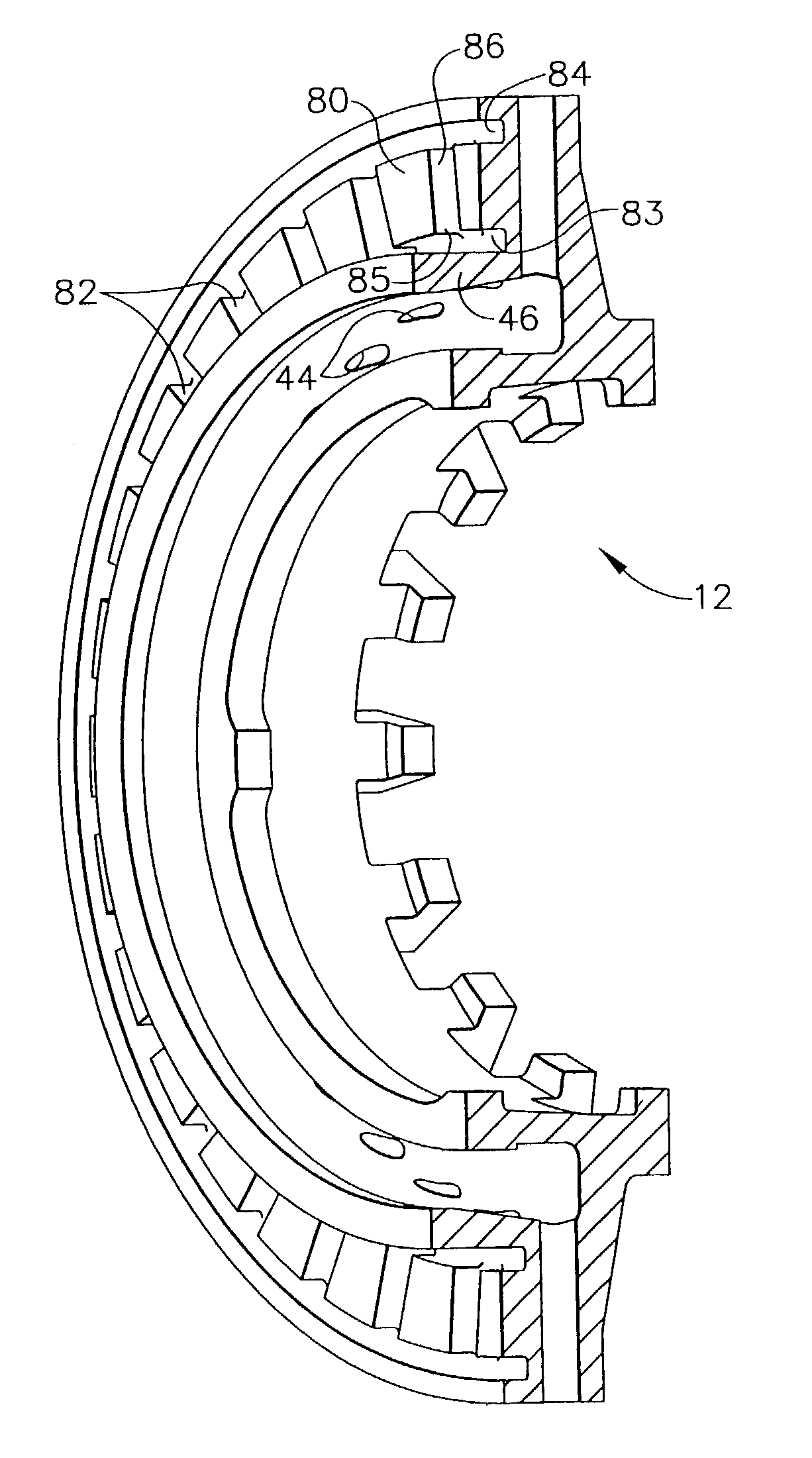
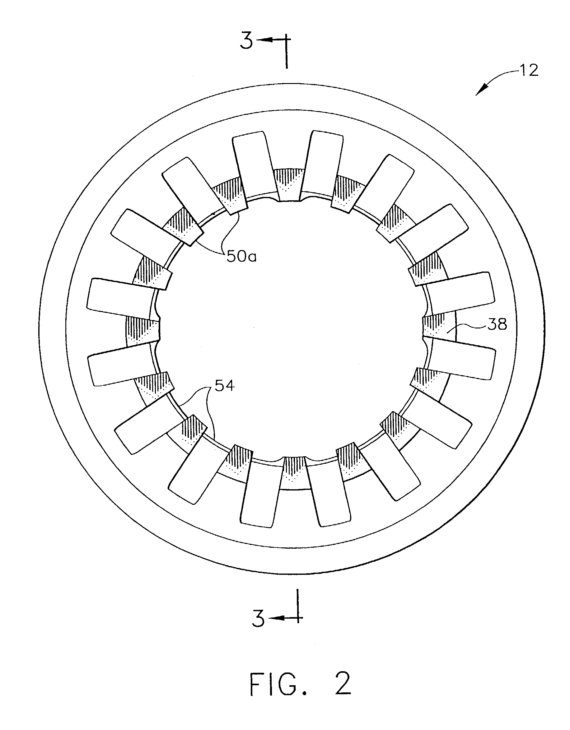
[0010]In one embodiment, the slinger rotor has a radially outward extending slinger ring with an outboard seal face which faces the inboard end of the end wall of a bearing housing. The seal face has radially oriented slots and a circumferential groove or grooves. During rotation of the slinger rotor, the radially oriented slots, combined with circumferential grooves, draw oil away from the area in between the seal face of the slinger ring and the inboard side of the end wall of the bearing housing. In this area, the negative pumping action has traditionally saturated the seal and caused leakage in high misalignment applications. The circumferential grooves also reduce air pumping at the face by allowing air to flow circumferentially to match the nutation (or oscillatory movement) of the rotor.

Problems solved by technology

In this area, the negative pumping action has traditionally saturated the seal and caused leakage in high misalignment applications.

Method used


Image

  • Non-contacting clearance seal for high misalignment applications
  • Non-contacting clearance seal for high misalignment applications
  • Non-contacting clearance seal for high misalignment applications

Examples


Embodiment Construction

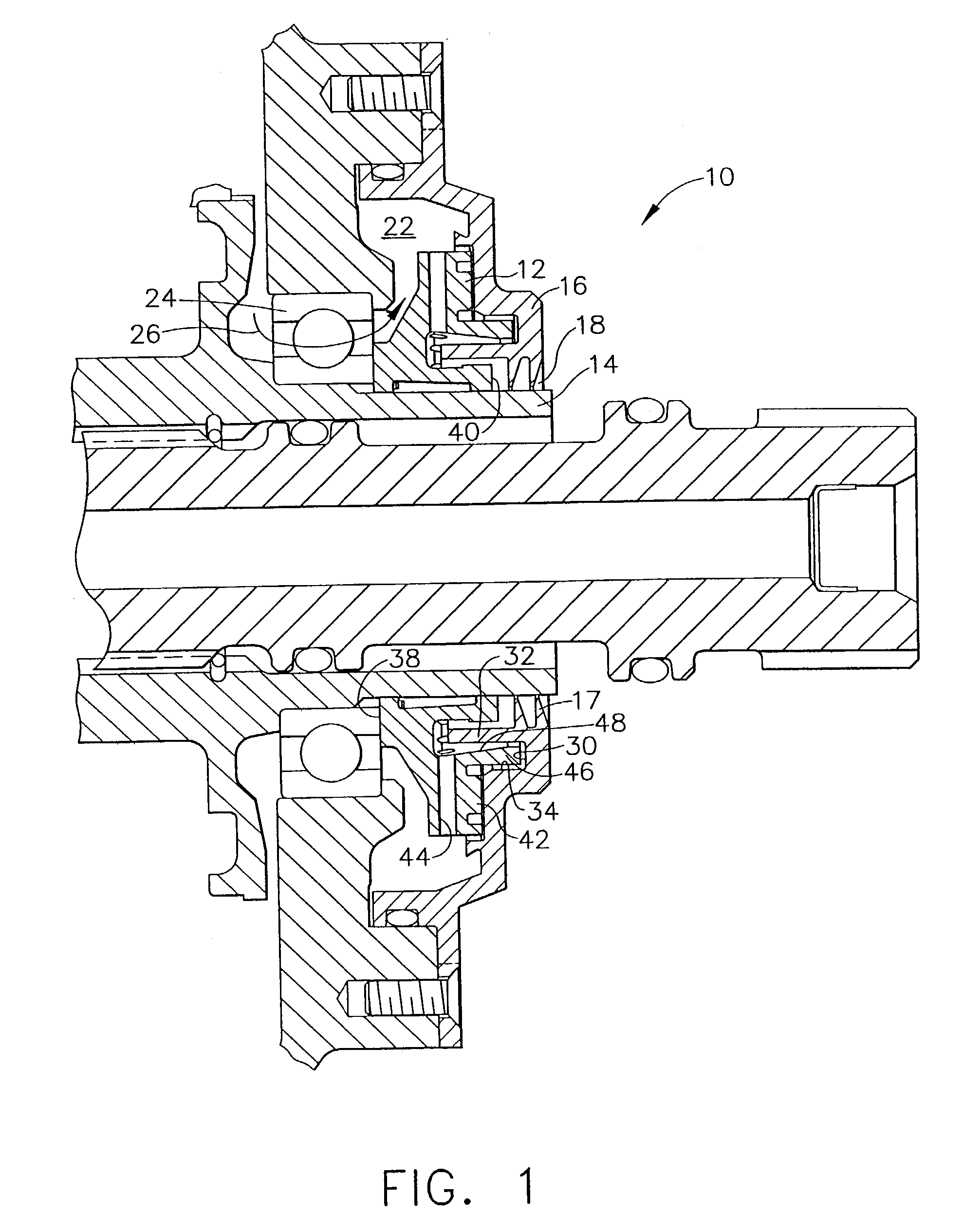
[0021]As shown in the exemplary drawings, an improved oil seal arrangement is provided for use in a turbomachine or the like identified generally in FIG. 1 by the reference numeral 10. The oil seal includes a slinger rotor 12, for sealing passage of a rotatable shaft 14 through an end wall 16 of a bearing housing for the turbomachine. The slinger rotor 12 is mounted on the shaft 14 for rotation therewith, and includes one or more dynamic air-oil separators for preventing oil from reaching a shaft passage 18 formed in the housing end wall 16.

[0022]FIG. 1 generally shows the rotatable shaft 14 extending through the shaft passage 18 in the end wall 16 of the bearing housing. The end wall 16 cooperates with other elements of the bearing housing to define a substantially enclosed but typically vented space or volume 22 within which the shaft 14 is rotatably supported by appropriate journal and / or thrust bearings 24. An oil circulation system delivers lubricating oil along a flow path 26 ...


PUM


Abstract

An improved oil seal is provided for sealing passage of a rotatable shaft through an end wall of a bearing housing in a turbomachine or the like, wherein the shaft is rotatably supported within the bearing housing by oil-lubricated bearings. The improved oil seal comprises a dynamic oil-air separator and a slinger rotor mounted on the shaft for rotation therewith, the slinger rotor having an outwardly extending slinger ring with an outboard seal face with radially oriented slots and a circumferential groove or grooves.

Description

RELATED APPLICATIONS[0001]This is a divisional of and claims priority from application Ser, No. 09 / 932,829 entitled “Non-Contacting Clearance Seal For High Misalignment Applications”, filed Aug. 16, 2001 now U.S. Pat. No. 6,629,816 which is incorporated herein by reference.FIELD OF THE INVENTION[0002]This invention relates generally to improvements in oil seals and related seal systems for preventing oil leakage in connection with rotating shafts, and particularly in connection with relatively high speed rotating shafts in turbomachines and the like. More specifically, this invention relates to an improvement in oil seals utilizing principles of dynamic air-oil separation to seal passage of a rotatable shaft through an end wall of a bearing housing in high misalignment applications.BACKGROUND OF THE INVENTION[0003]In turbomachinery, a rotatable shaft is commonly supported by appropriate journal and thrust bearings mounted within a bearing housing, wherein oil is circulated from a su...

Claims


Application Information

Patent Timeline
IPC IPC(8): F16J15/40F16J15/447
CPCF16J15/164F16J15/4476F16C33/80F16C19/06
Inventor LANGSTON, TODD A.GIESLER, WILLIAM L.
Owner HONEYWELL INT INC
Learn More