Strut/shock crossmember

a crossmember and strut technology, applied in the direction of suspension arms, transportation and packaging, pivoted suspension arms, etc., can solve the problem of relatively few known applications, if any, of a strut/shock brace being utilized, and achieve the effect of improving vehicle handling and stiffness of the vehicle chassis

Active Publication Date: 2006-06-06
NOBLE ERIC
View PDF3 Cites 12 Cited by
  • Summary
  • Abstract
  • Description
  • Claims
  • Application Information

AI Technical Summary

Benefits of technology

[0015]According to other aspects of the present invention, the main body of the mounting flange is conformally attached to a portion of the lower body of the vehicle. In another aspect of the present invention, no modifications are required on the vehicle to install the crossmember device. Additionally, the crossmember device may be positioned contiguously and laterally next to a backside of a rear seat of the vehicle such that trunk spaced remains unobstructed. Moreover, according to another aspect of the present invention, when the crossmember device is installed in the vehicle, the stiffness of the vehicle chassis is increased, and as a result, the handling of the vehicle is improved. Furthermore, according to another aspect of the present invention, the crossmember device is positioned contiguously and laterally next to a cabin-to-trunk body bulkhead of the vehicle.

Problems solved by technology

Although there are many prior art examples of strut / shock braces available for “tieing” the front left and right strut / shock towers of a vehicle together, there are relatively few known applications, if any, of a strut / shock brace being utilized between the two rear strut / shock towers of a vehicle.

Method used


Image

  • Strut/shock crossmember
  • Strut/shock crossmember
  • Strut/shock crossmember

Examples


Embodiment Construction

[0026]The particulars shown herein are by way of example and for purposes of illustrative discussion of the embodiments of the present invention only and are presented in the cause of providing what is believed to be the most useful and readily understood description of the principles and conceptual aspects of the present invention. In this regard, no attempt is made to show structural details of the present invention in more detail than is necessary for the fundamental understanding of the present invention, the description taken with the drawings making apparent to those skilled in the art how the several forms of the present invention may be embodied in practice.

Overview of the Present Invention

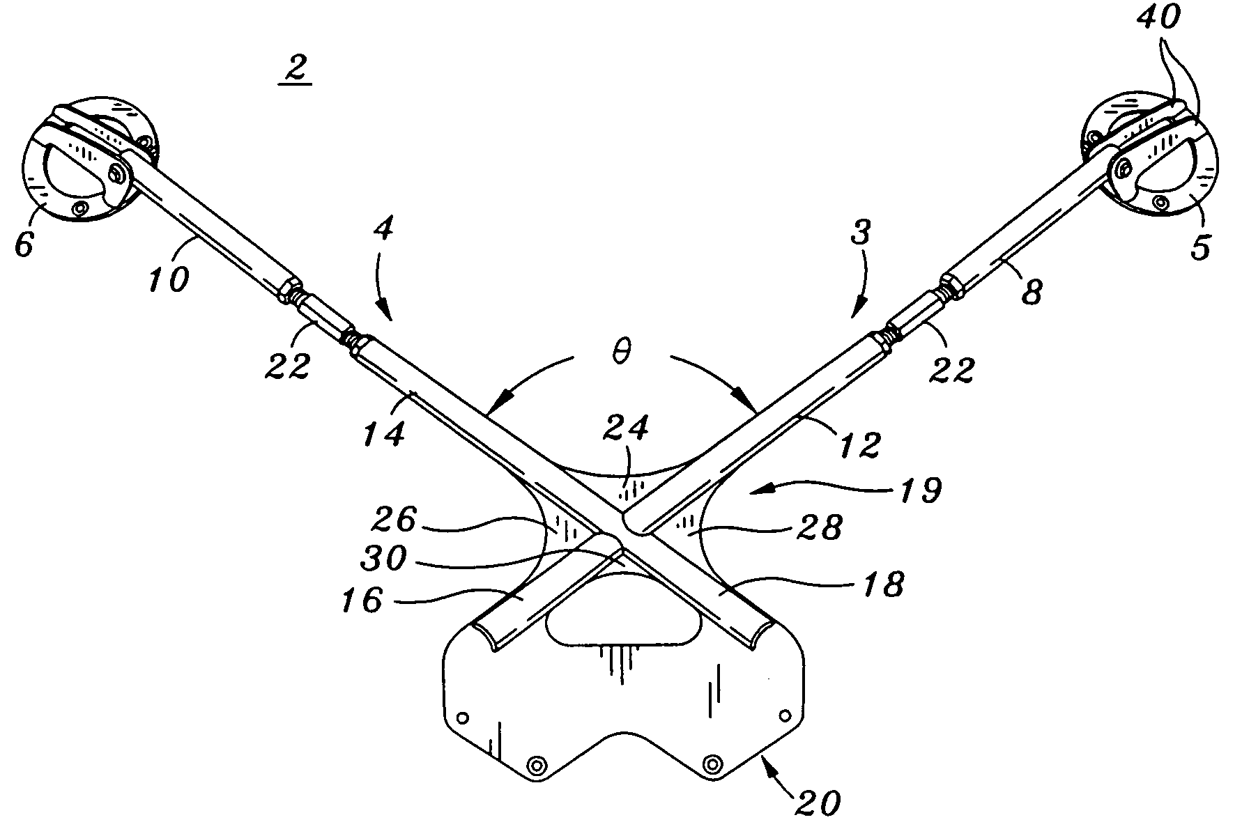
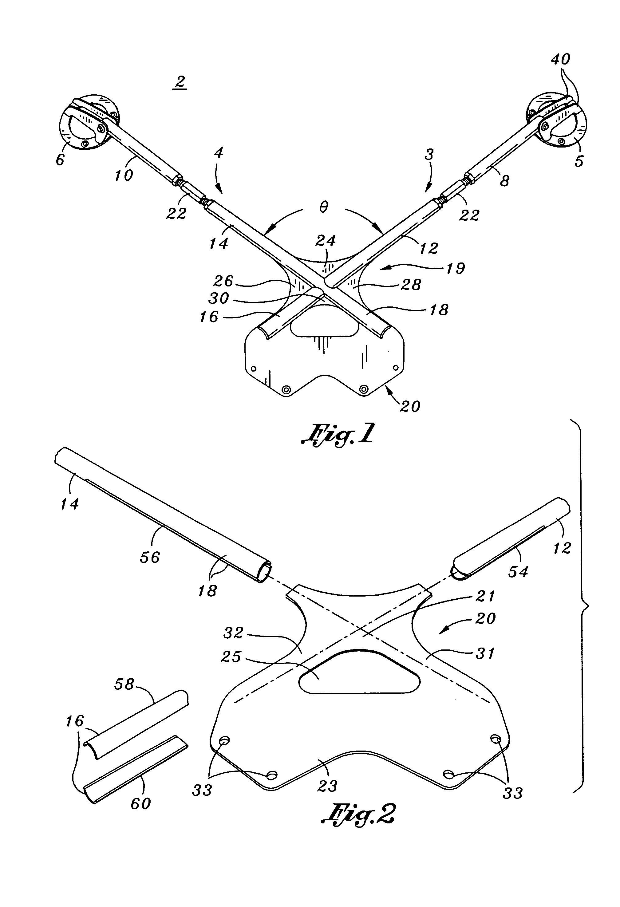
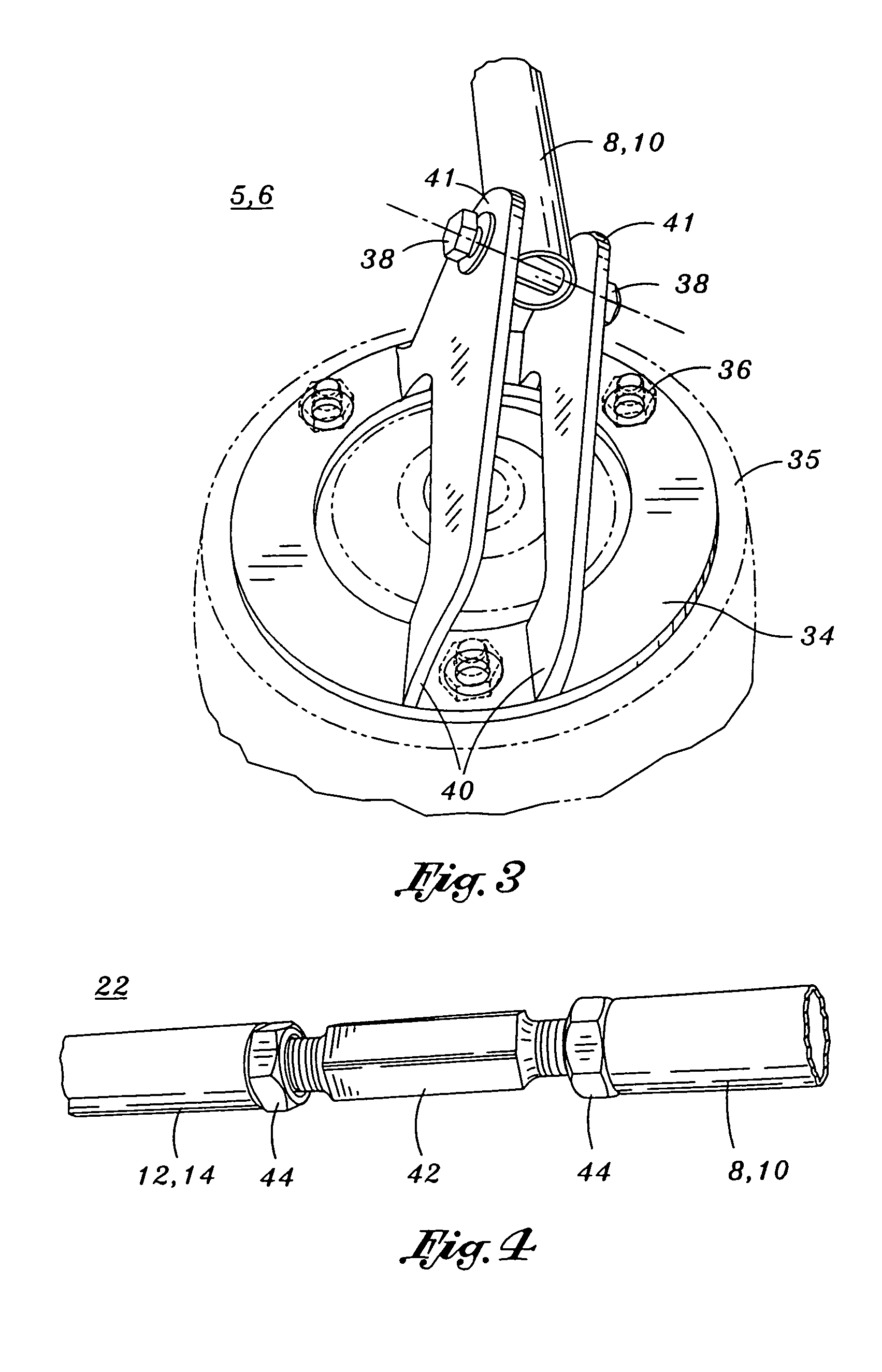
[0027]An exemplary embodiment of an adjustable tubular strut / shock crossmember device 2 (see FIG. 1) is provided which is adapted to be installed between a pair of suspension strut or shock towers 35 from a vehicle (see FIG. 3). The strut / shock crossmember 2 is preferably oriented in one o...


PUM


Abstract

A crossmember device is provided which is adapted to be installed between a pair of strut / shock towers of a vehicle. The crossmember device includes a left brace and right brace each having an upper, intermediate and lower portion. The left and right brace are interconnected in a X configuration, wherein the center of the interconnection is between the intermediate and lower portions of the left and right brace. A planar body mounting flange provides gusseting structure to interconnect the left and right brace. A strut / shock tower flange assembly is swivel attached to each distal end of the upper portions of the left and right brace.

Description

CROSS-REFERENCE TO RELATED APPLICATIONSSTATEMENT RE: FEDERALLY SPONSORED RESEARCH / DEVELOPMENTBACKGROUND OF THE INVENTION[0001]1. Field of the Invention[0002]The present invention relates to strut and / or shock braces for automobiles. In particular, the present invention relates to a generally vertically or vertically inclined crossmember brace adapted to be positioned between the rear strut and / or shock towers of a vehicle.[0003]2. Background of the Invention[0004]There are numerous aftermarket products available that are designed especially for improving the suspension and chassis of an automobile. One may subtly improve the handling characteristics of a vehicle by simply adding low-profile tires and high-performance struts / shocks. Or, if one desires to transform an automobile into a more aggressively handling vehicle that mimics the handling characteristics of a race car, additional aftermarket components may be installed, such as racing springs, high performance bushings, heavy-du...

Claims


Application Information

Patent Timeline
Patent Type & Authority Patents(United States)
IPC IPC(8): B60G21/05B60G15/07B62D1/00B62D25/08
CPCB60G15/07B62D25/087B62D25/082B60G2206/014B60G2206/60
Inventor NOBLE, ERIC
Owner NOBLE ERIC
Why Eureka
Try Eureka