
Silent chain

a technology of silent chain and chain link, which is applied in the direction of driving chain, belt/chain/gearing, chain element, etc., can solve the problems of insufficiently elaborate manufacturing procedure for chain link production, inability to meet the needs of chain link production, and restricted bearing surface area, so as to improve silent chain characteristics, improve bearing surface, and improve wear properties

Active Publication Date: 2006-06-06
BORGWARNER INC
View PDF22 Cites 22 Cited by
  • Summary
  • Abstract
  • Description
  • Claims
  • Application Information

AI Technical Summary

Benefits of technology

[0021]Accordingly, a chain assembly having a first set of links, each link having a pair of apertures, wherein each aperture is disposed to receive a bushing having an inner diameter with an inner surface and an outer diameter with an outer surface, the bushing being interposed between each aperture and a pin; and a second set of links, each link having a pair of apertures, wherein each aperture is disposed to receive the bushing having the inner diameter with the inner surface and the outer diameter with the outer surface, the bushing being interposed between each aperture and the pin is provided. The chain assembly further includes a set of outside links positioned on the outside of the chain assembly having the first set of links and the second set of links interposed therebetween. The pin has a surface disposed to contact the inner surface of the bushing. The outer surface of the bushing is disposed to contact and move relative to a surface of the inner walls of the each aperture of each of the second set of links. Thereby increased bearing surface and improved silent chain characteristics are provided. The improved characteristics include better wear properties than a roller chain, and much better wear properties than a conventional silent chain. The noise, vibration, harshness (NVH) characteristics of a conventional silent chain are maintained.

Problems solved by technology

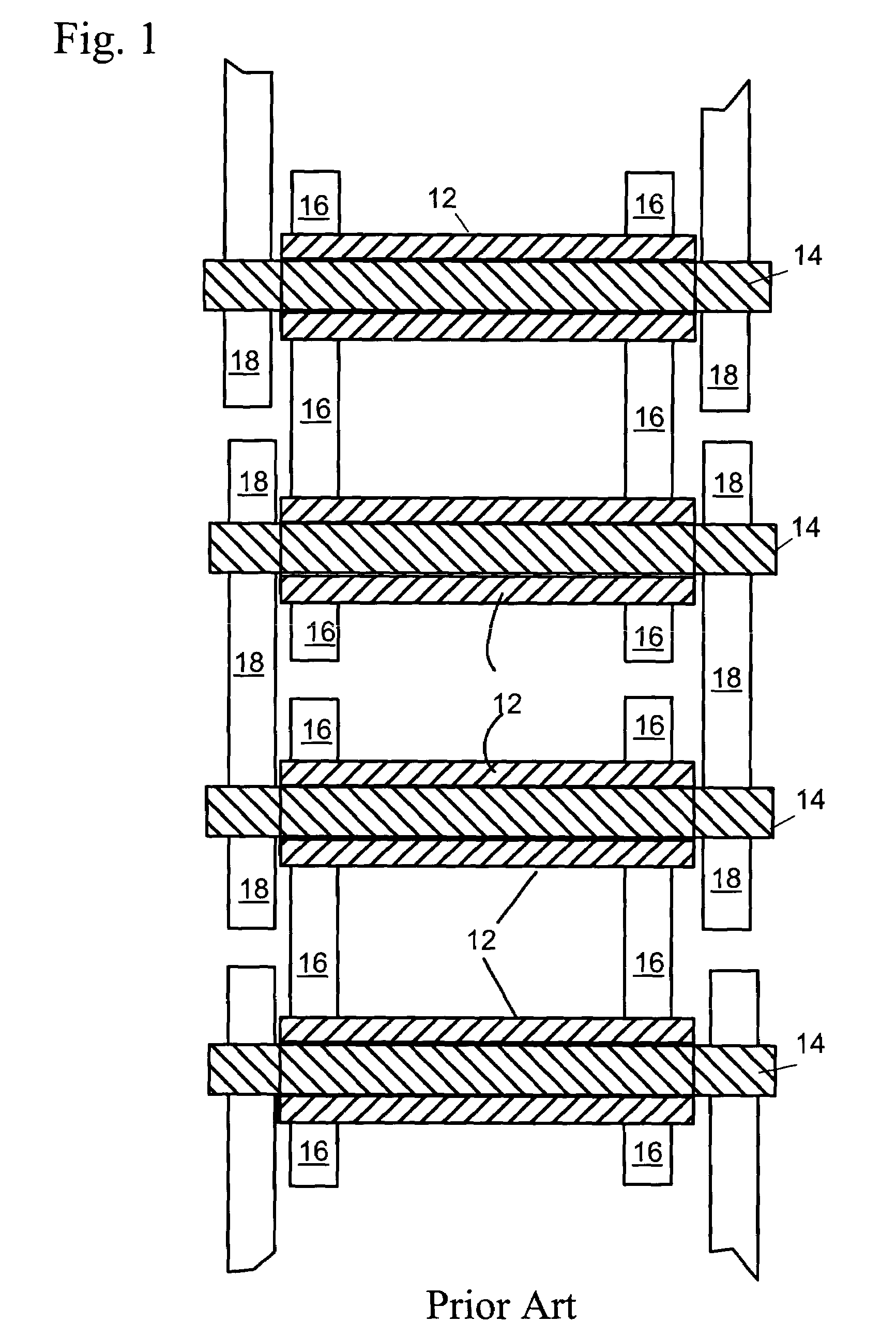
However, the peripheral surface of U.S. Pat. No. 6,450,911 B2 has disadvantages including increased width of each strand of chain.
Further, it would inherently require more elaborate manufacturing procedure to produce the chain links.
However, the pin outer peripheral surface in contact with the inner peripheral surface of the mating pin hole of the guide link plate and the articular links has disadvantages including the bearing surface area is still restricted to the above described contact.
In roller chain drives, the noise can be caused, in part, by the impact sound generated by the collision of the chain and the sprocket at the onset of meshing.
The mass of chain rollers contacting the sprocket at a particular moment or time increment affect the noise level as well.
However, roller chains are usually limited to applications where noise generation may not be of the primary concern.
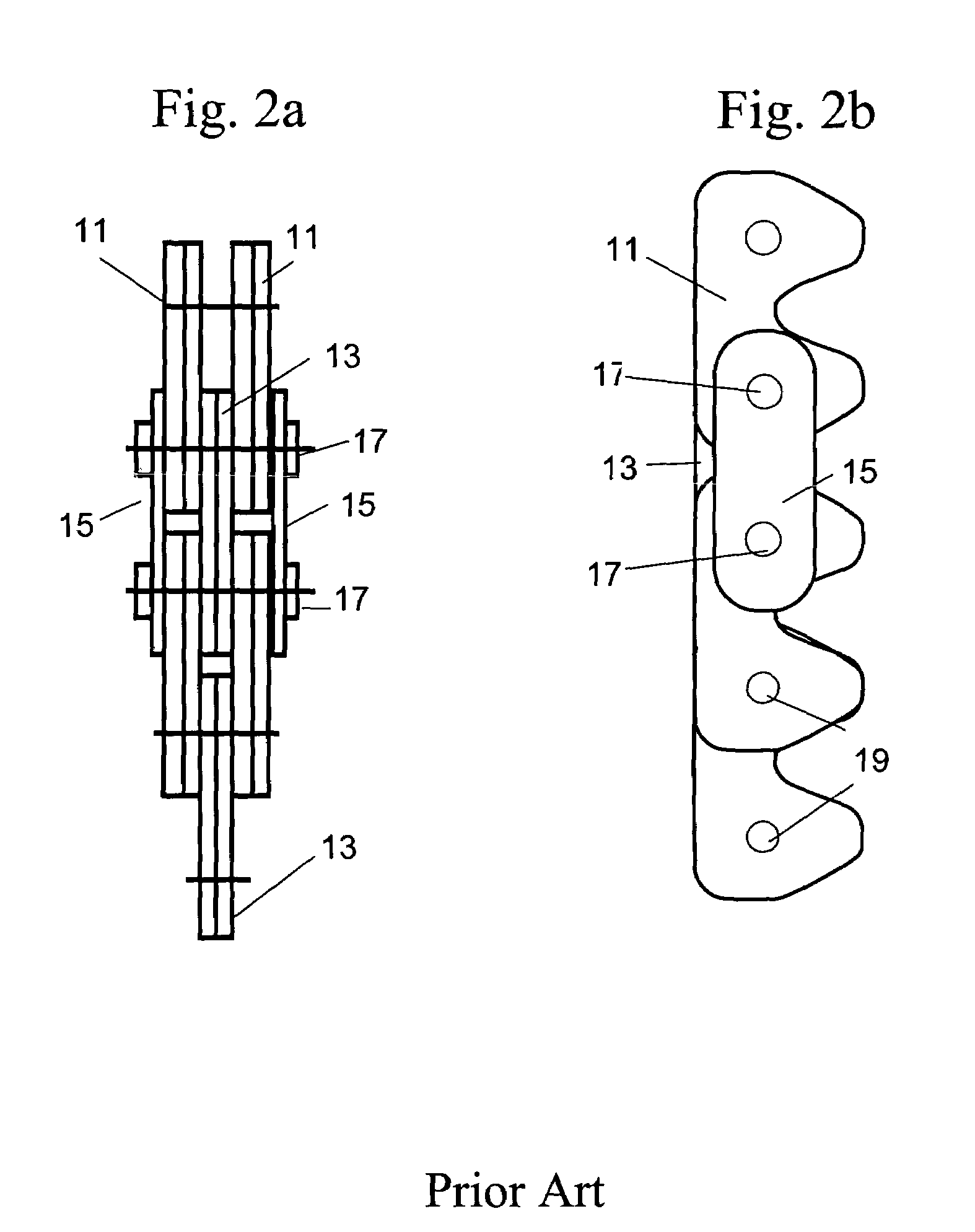
Silent chains generally have poor wear performance due to the relatively short and poor quality bearing area between the non-guide row inside link plates and the pin.

Method used


Image

  • Silent chain
  • Silent chain
  • Silent chain

Examples


first embodiment

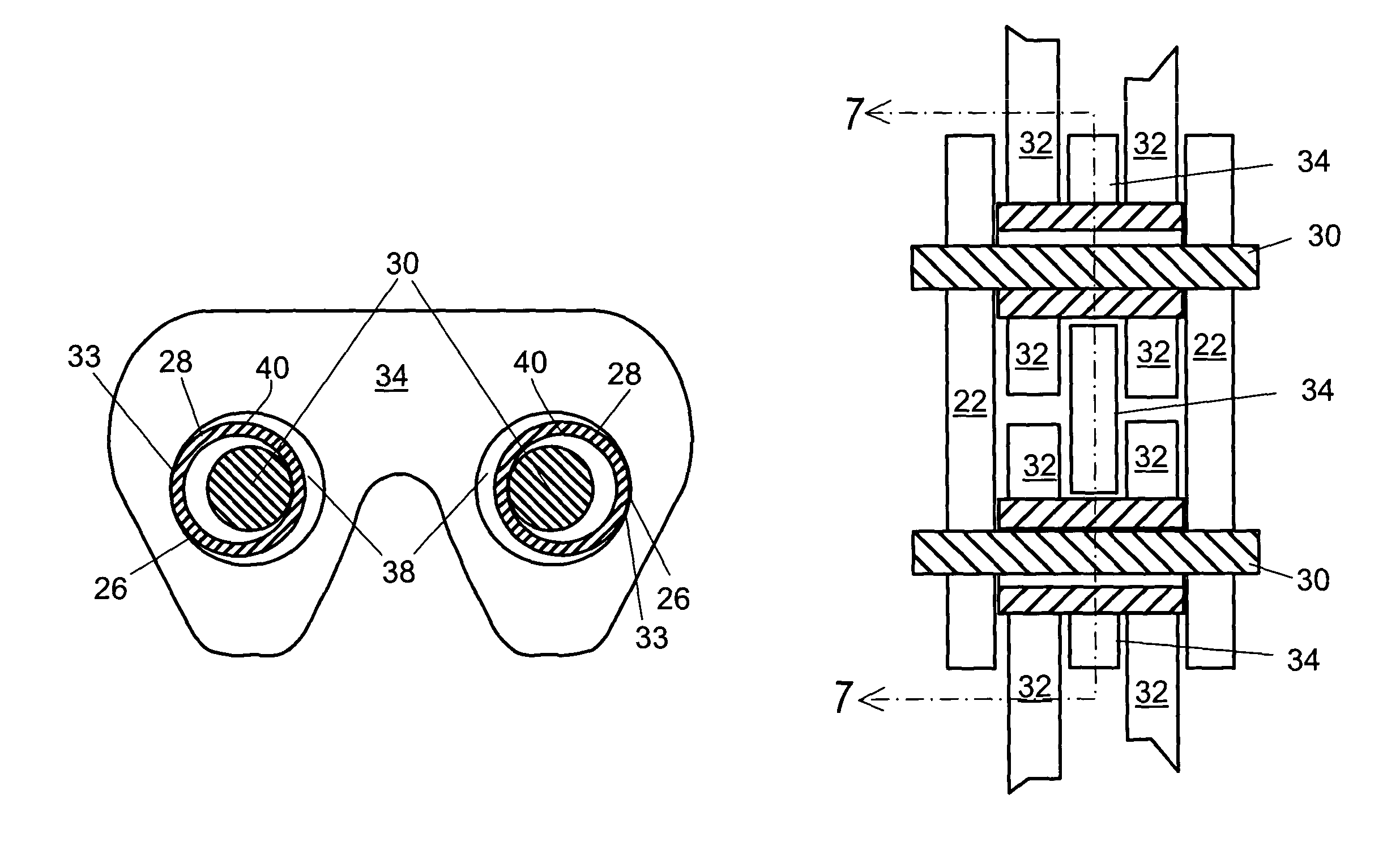
[0032]One embodiment of the present invention that discloses the fundamental concept is shown in FIG. 3. In this first embodiment, a set of links are provided. Two pairs of inside links (ISL) 32 on the non-guide row are provided. Two inside links (ISL) 34 on the guide row are also provided. Additionally, a pair of outside guide links 22 are provided. Links 34 are located in the center of the endless chain having a center line 100 partitioning the two links 34. Center line 100 also partitions links 22 and links 32.

[0033]In the present figure, the chain may be guided on a sprocket (not shown) by the pair of guide links 22. Each link including guide link 22 has a pair of apertures or annular openings at each end. Within each aperture, there is a surface. Further, each aperture receives a connecting member such as a pin 30, or bushing 28, for connecting various links into an endless chain. Each link 32 has a pair of apertures or annular openings at each end. Within each aperture of link...

second embodiment

[0036]A second embodiment is shown in FIG. 4. Similar to FIG. 3, an endless chain having links 22, 32, and 34 are provided. Additionally, bushings 28 and pins 30 are provided as well. As can be seen, only two links 32 are used in each non-guide row. Each link 32 is interposed between link 22 and link 34. All the pairs of links are substantially symmetrical with respect to center line 100.

third embodiment

[0037]Referring to FIGS. 5a through 5c, the present invention is shown. In this embodiment, the endless chain is similarly guided on the sprocket (not shown) by a center link 20 on the guide row, which fits into a groove (also not shown) of the sprockets. Center link 20 is non-inverted in shape as shown. The remaining links of the present figure are of the inverted tooth type. Inside link 24 is rigidly affixed upon bushing 28. For example, link 24 may be press fit on bushing 28. Therefore, no relative movements between the OD of bushing 28 and inside surface of link 24 occur. The use of center guide link in silent chains is well known in the art. However, the present invention provides for the center guide link 20 to fit over the outside diameter surface 26 of bushings 28, thereby providing additional bearing area to carry load. The total bearing area of this design is the sum of the pin 30 to bushing 28 bearing area (the area disposed for contact between the inner surface of bushin...


PUM


Abstract

A Hybrid Roller / Silent chain that has the wear resistance of a roller chain combined with the noise performance of a silent chain. This is accomplished with the use of bushings that allow increased bearing area for the articulating members of the chain, specifically by allowing load to be transmitted through both the inside and outside diameter of the bushing in the same plane.

Description

BACKGROUND OF THE INVENTION[0001]1. Field of the Invention[0002]The invention pertains to the field of silent chains. More particularly, the invention pertains to an improvement over a commonly available silent chain. Yet more particularly, the invention pertains to an improvement over a commonly available silent chain having bushings that permit increased bearing area for articulating members of the chain.[0003]2. Description of Related Art[0004]Roller chains and silent chains are known. Both types of chains have known applications in the automobile industry.[0005]U.S. Pat. No. 6,450,911 B2 teaches a peripheral surface of a silent chain including a number of interleaved rows of link plates articulately connected together by joint pins. Each of the link plates has a pair of teeth and a pair of pin holes. The link plate further has a tubular portion protruding continuously from one surface of the link plate and defining a peripheral surface of each of the pin holes. The tubular porti...

Claims


Application Information

Patent Timeline
Patent Type & Authority Patents(United States)
IPC IPC(8): F16G13/04F16G13/06
CPCF16G13/04
Inventor BUTTERFIELD, ROGER P.
Owner BORGWARNER INC
Learn More