Electronic clutch-to-clutch transmission control system

a transmission control and electronic technology, applied in the field of transmission systems, can solve the problems of large packaging envelopes, over-complex configuration, and increased cos

Inactive Publication Date: 2006-06-06
GM GLOBAL TECH OPERATIONS LLC
View PDF7 Cites 17 Cited by
  • Summary
  • Abstract
  • Description
  • Claims
  • Application Information

AI Technical Summary

Problems solved by technology

However, this configuration is overly complex, increases cos...

Method used


Image

  • Electronic clutch-to-clutch transmission control system
  • Electronic clutch-to-clutch transmission control system
  • Electronic clutch-to-clutch transmission control system

Examples


Embodiment Construction

[0014]The following description of the preferred embodiment is merely exemplary in nature and is in no way intended to limit the invention, its application, or uses. For purposes of clarity, the same reference numbers will be used in the drawings to identify similar components.

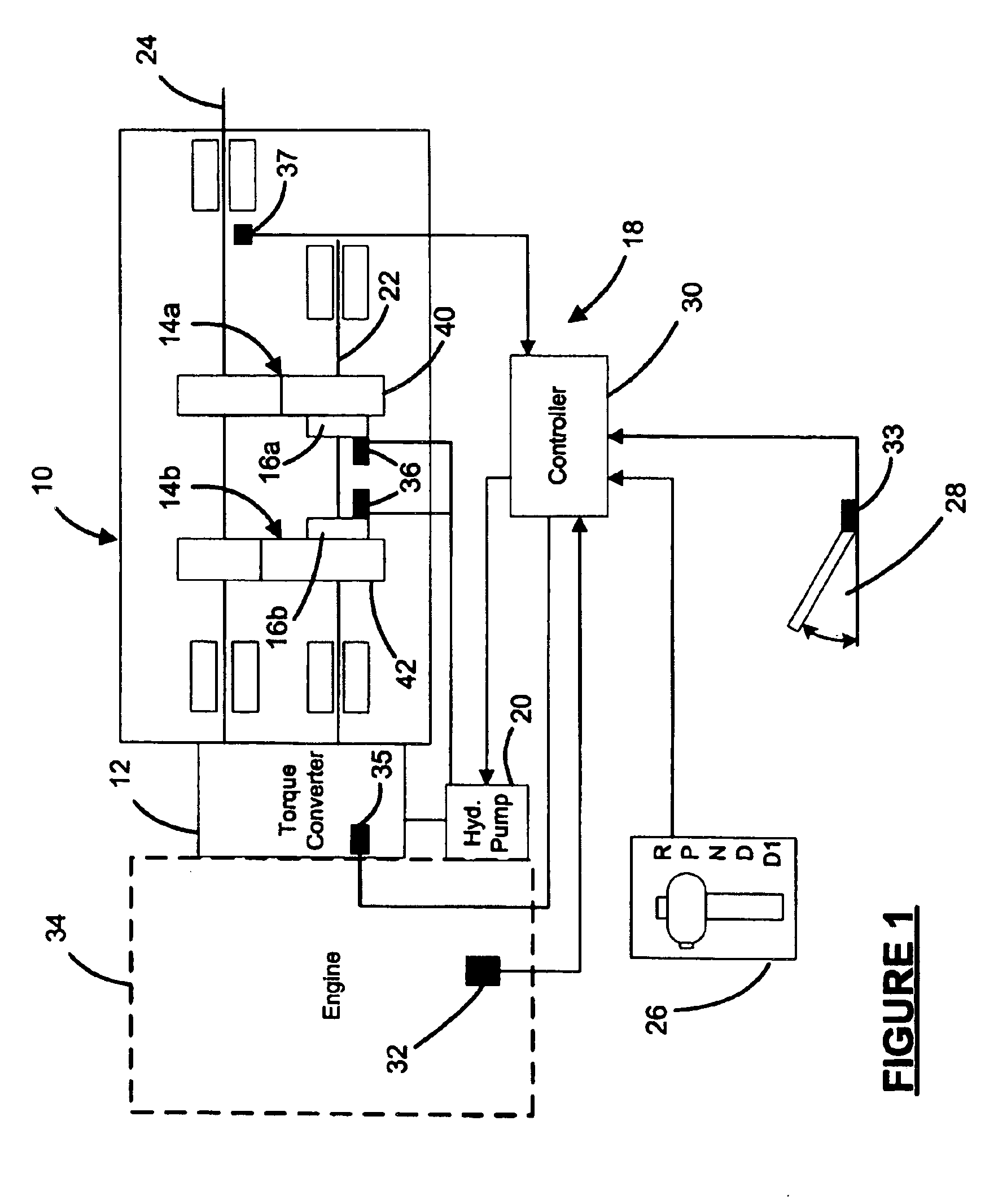
[0015]Referring now to FIG. 1, an exemplary automatic transmission 10 includes a torque converter 12, a plurality of gear sets 14a, 14b, hydraulically-actuated multiple clutches 16a, 16b, a transmission control system 18, and a hydraulic pump 20. The hydraulic pump 20 may be driven by the engine or an electric motor. The torque converter 12 enables start-off, provides torque multiplication, and absorbs harmonic vibrations within the vehicle drivetrain.

[0016]The gear sets 14a, 14b are located between an input shaft 22, which is connected to the torque converter 12, and an output shaft 24. The gear sets 14a, 14b enable the output shaft 24 to be driven at multiple gear ratios. The transmission control system 18 s...


PUM


Abstract

A transmission system includes a first clutch, a second clutch, and a controller. The controller communicates with the first and second clutches and commands a gear shift. The controller calculates a torque phase time for the gear shift and determines a desired torque trajectory within said torque phase time. The controller determines on-coming torque values for the second clutch and off-going torque values for the first clutch to achieve the desired torque trajectory within the torque phase time. The controller calculates an on-coming clutch pressure based on the on-coming torque value, and an off-going clutch pressure based on the off-going torque value. The controller delays actuation of the first and second clutches to compensate for hydraulic delays.

Description

TECHNICAL FIELD[0001]The present invention relates to transmission systems, and more particularly to a transmission system with improved clutch-to-clutch shift control.BACKGROUND OF THE INVENTION[0002]Automatic transmissions include a plurality of gears and associated components that are manipulated to drive an output shaft using different gear ratios. A transmission controller monitors vehicle operating conditions and driver input to determine whether an up-shift or a down-shift should occur. During a shift, an on-coming component gradually engages the next gear as an off-going component gradually disengages the present gear.[0003]Traditionally, a one-way clutch or diode is implemented as an off-going component to transfer torque through the powertrain. The release of the off-going component is controlled based upon the rate of the on-coming component during the shift. Conventional transmission systems use compliance devices, such as accumulators, wave plates, and orifices, and hyd...

Claims


Application Information

Patent Timeline
IPC IPC(8): F16H61/00F16H61/04F16H61/06F16H61/28F16H61/08F16H61/68F16H63/12
CPCF16H61/061Y10T477/6937Y10T477/6895Y10T477/69383
Inventor WHITTON, MATTHEW D.
Owner GM GLOBAL TECH OPERATIONS LLC
Why Eureka
Try Eureka