Shock absorbent roller thumb wheel

a technology of roller thumb wheel and roller bearing, which is applied in the direction of contact vibration/shock damping, instruments, computing, etc., can solve the problems of thumb wheel, unusable mobile devices, and impa

Inactive Publication Date: 2006-06-06
MALIKIE INNOVATIONS LTD
View PDF13 Cites 105 Cited by
  • Summary
  • Abstract
  • Description
  • Claims
  • Application Information

AI Technical Summary

Problems solved by technology

When the mobile device is accidentally dropped, the impact can occur at the protruding rolling thumb wheel.
The impact force applied to the thumb wheel can damage an assembly the thumb wheel is attached to, rendering the mobile device unusable.
More specifically, the impact force can cause the thumb wheel assembly to break off a printed circuit board or other device element to which it is attached.

Method used


Image

  • Shock absorbent roller thumb wheel
  • Shock absorbent roller thumb wheel
  • Shock absorbent roller thumb wheel

Examples


Embodiment Construction

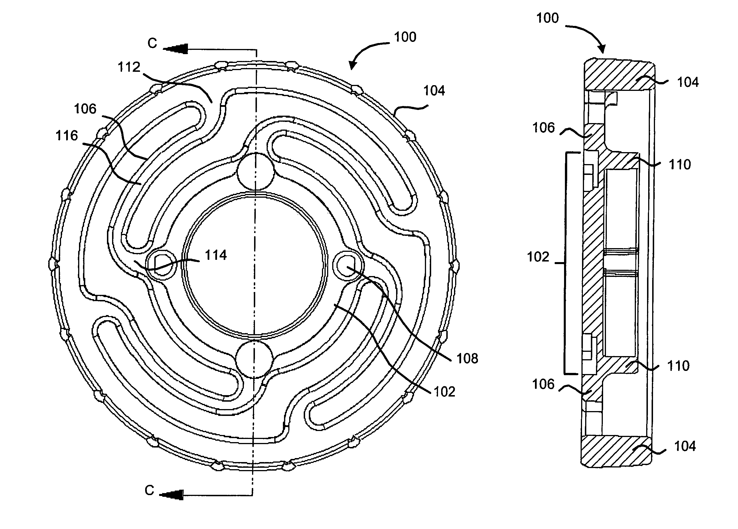
[0023]A shock absorbing roller thumb wheel is disclosed. The shock absorbing thumb wheel includes a central hub that can be secured to an electro-mechanical switch, a rim encircling the central hub, and force dispersion spokes extending from the central hub and connected to the rim. The configuration of the force dispersion spokes and the resilient material of the force dispersion spokes and the rim allow for radial and lateral deflection of the rim in response to an applied impact force. Therefore, as an impact force is absorbed by the radial and lateral deflection of the rim and spokes, less impact force is transferred to solder joints connecting the electro-mechanical switch to a printed circuit board, such as in a typical switch installation. Hence, the probability of solder joint failures is reduced, and the lifetime of the device that uses the thumb wheel can be extended.

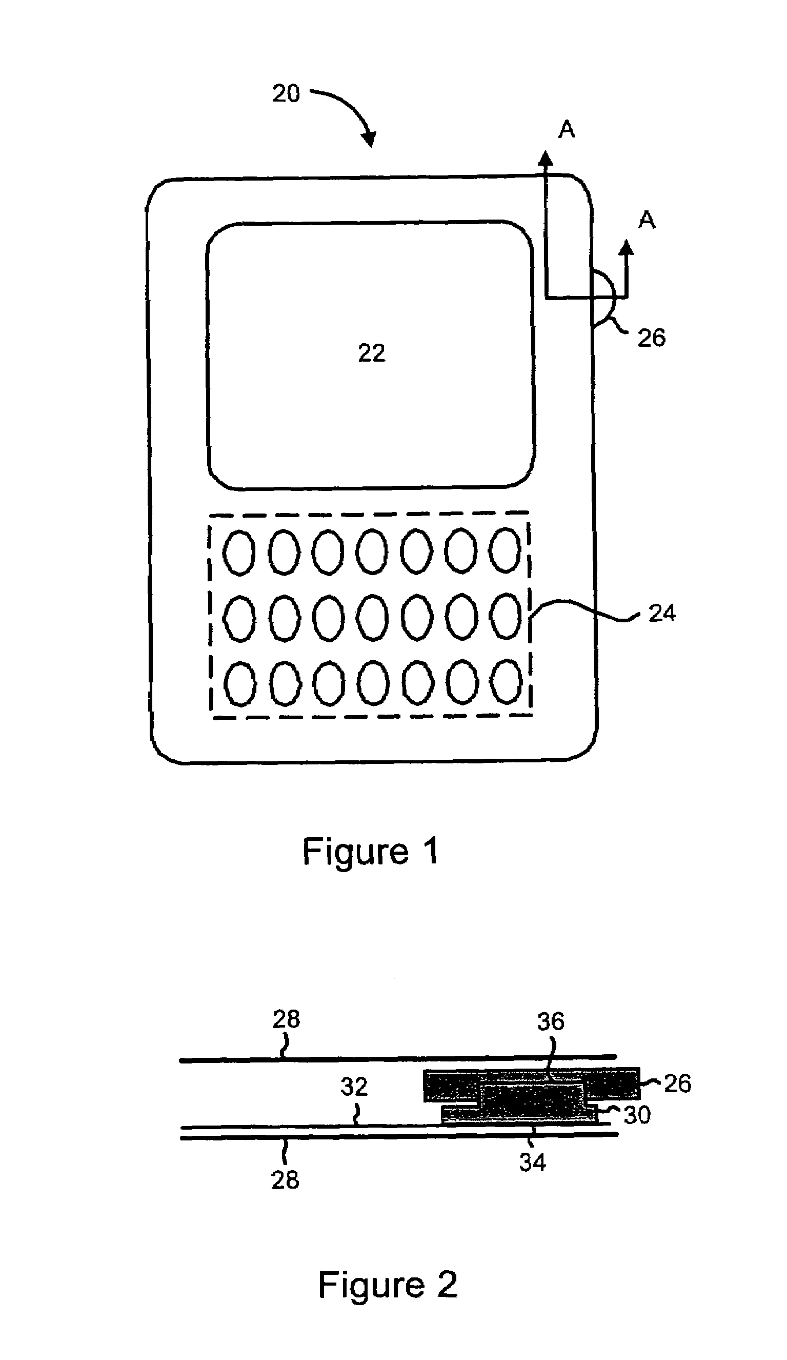
[0024]FIG. 1 is a block diagram of a mobile device having a roller thumb wheel. The device 20 includes an L...


PUM


Abstract

A shock absorbing roller thumb wheel is disclosed. The shock absorbing thumb wheel includes a central hub that can be secured to an electro-mechanical switch, a rim encircling the central hub, and force dispersion spokes extending from the central hub and connected to the rim. The configuration of the force dispersion spokes and the resilient material of the force dispersion spokes and the rim allow for radial and lateral deflection of the rim in response to an applied impact force. The impact force is thereby at least partially absorbed by the radial and lateral deflection of the rim and spokes, such that less impact force is transferred to connections between the electro-mechanical switch and any assembly to which the switch is attached. Hence, the probability of connection failures is reduced, and the lifetime of a device that uses the thumb wheel can be extended.

Description

CROSS-REFERENCE TO RELATED APPLICATION[0001]This application is a continuation of U.S. application Ser. No. 10 / 410,094, filed Apr. 9, 2003, which issued as U.S. Pat. No. 6,828,518 on Dec. 7, 2004, the disclosure of which is incorporated herein by reference in its entirety.FIELD OF THE INVENTION[0002]The present invention generally relates to roller thumb wheels for electronic devices.BACKGROUND OF THE INVENTION[0003]Many mobile electronic devices such as personal digital assistants, cell phones, and other wireless devices utilize various input means for allowing a user to select or execute functions upon the device. Such input means can include keyboards for entering alpha-numeric text, dedicated function buttons, directional keypad buttons and roller thumb wheels.[0004]Roller thumb wheels are desirable since they permit single-handed operation of the device. In particular, the thumb wheel is placed at a position on the device such that the user can actuate the thumb wheel with a th...

Claims


Application Information

Patent Timeline
Patent Type & Authority Patents(United States)
IPC IPC(8): H01H19/58H01H3/60H01H19/00
CPCH01H19/001H01H3/60
Inventor MA, DAVE M.TEMPELMAN, HERREBERTUSHOLMES, JOHN A.
Owner MALIKIE INNOVATIONS LTD
Why Eureka
Try Eureka