Vehicle illuminating device comprising an auxiliary reflector for lateral deflection of a light portion of a light source

a technology of auxiliary reflector and vehicle lamp, which is applied in the direction of fixed installation, lighting and heating apparatus, instruments, etc., can solve the problems of increased repair and maintenance expenses, increased lateral visibility, and increased lateral visibility, and achieves a high level of compactness of vehicle lamps

Active Publication Date: 2010-11-18
VOLKSWAGEN AG
View PDF5 Cites 13 Cited by
  • Summary
  • Abstract
  • Description
  • Claims
  • Application Information

AI Technical Summary

Benefits of technology

[0017]According to various embodiments, based on at least one light source the emitting angle of at least a functional illuminating area of a vehicle lamp can be aligned such that the light of this light source in addition to its main alignment along the vehicle also is emitted laterally towards the outside of the motor vehicle in a at least perpendicular angle and comprising a brightness which meets the respective regulations of the lateral marking requirements, which is to mean to clearly mark the vehicle in a lateral direction and to thereby allow for a high level of compactness of the vehicle lamp.

Problems solved by technology

This requires additional expenses with respect to material and mounting, by which additional costs arise and correspondingly the repairs and maintenance expenses are increased in addition.
This is an additional lamp and therefore implies additional cost, wherein it moreover does not lead to an increase in lateral visibility.
This way indeed a better light emitting efficiency reducing the heat losses is reached, but a specific broadening of the light outlet angle is not effectively reached.
With this solution an additional reflector manufactured and mounted as an individual component is used, by which additional cost is generated.
Thereby indeed also the illuminating angle may be enlarged, but the attenuation of light due to light scattering may be too large, so that the brightness of a vehicle lamp may be afflicted.
Such additional optical means do not allow for to always, and not in each application, achieve the required broadening of the light outlet angle and thereby the required lateral visibility of the light signals.

Method used


Image

  • Vehicle illuminating device comprising an auxiliary reflector for lateral deflection of a light portion of a light source
  • Vehicle illuminating device comprising an auxiliary reflector for lateral deflection of a light portion of a light source
  • Vehicle illuminating device comprising an auxiliary reflector for lateral deflection of a light portion of a light source

Examples


Embodiment Construction

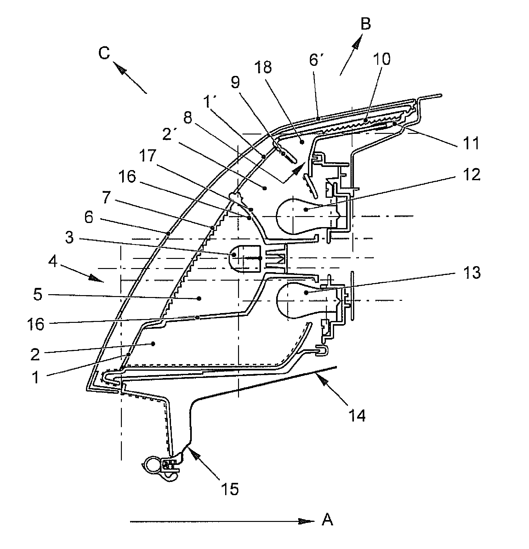
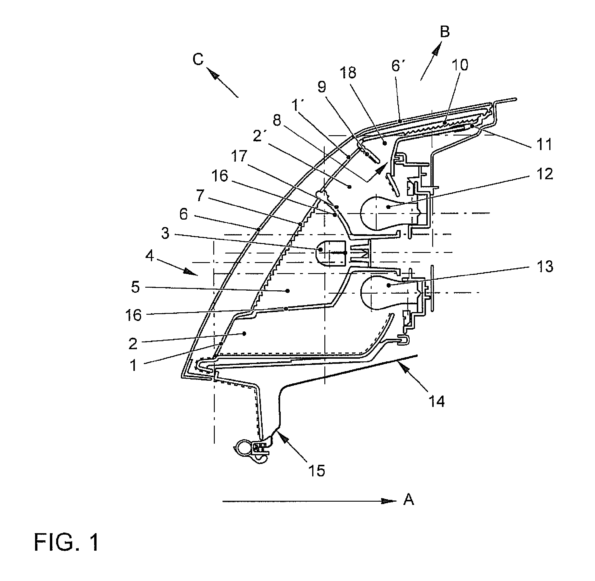
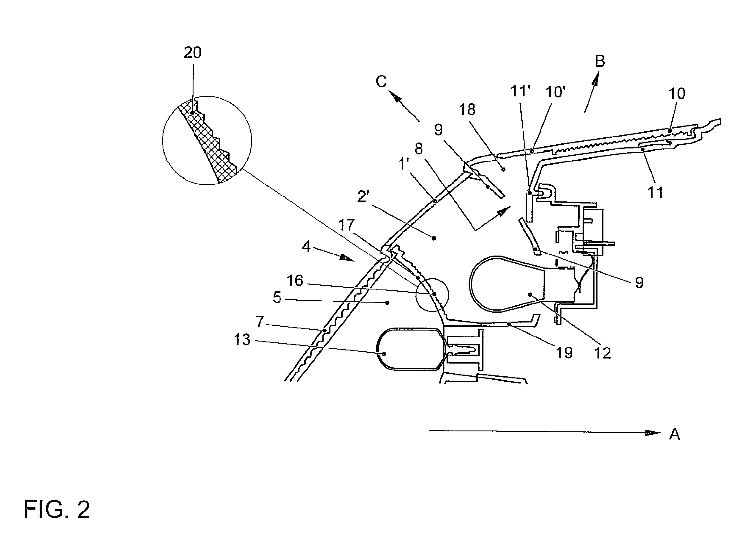
[0024]In a vehicle illuminating device for integrated mounting in each of a edge region of a motor vehicle its housing is provided with at least one chamber, at least one light source positioned in a bracket, at least one reflector, at least one intermediate light disc comprising therein optical means formed at least in partial regions, wherein the intermediate light disc comprises at least one signal function region dyed in a signal color, the electrical connection contacts and a cover housing disc arranged spaced from the intermediate light disc, by providing the at least one reflector according to various embodiments in a first chamber with at least one lateral section, which is provided in a essentially horizontal direction laterally facing away from the motor vehicle, the housing of the vehicle device comprises a lateral light region extended into the lateral region of the body of the vehicle, in which an additional lateral intermediate light disc is arranged, wherein the cover...


PUM


Abstract

A vehicle illuminating device for the integrated attachment in each edge region of a motor vehicle, has a housing with at least one chamber, a light source positioned in a bracket, a reflector, an intermediate light disc with a prism arranged therein in at least partial regions, wherein the intermediate light disc has at least one signal function region dyed in a signal color, and electric connection contacts and a cover housing disc are spaced from the light disc. The reflector has in a first chamber a lateral section provided in a predominantly horizontal, lateral direction facing away from the vehicle. The housing has a lateral light region extending into the lateral region of the vehicle body, an additional lateral intermediate light disc arranged in the region, wherein the cover housing disc covers also the lateral light region with the lateral intermediate light disc from the outside at a distance.

Description

CROSS-REFERENCE TO RELATED APPLICATIONS[0001]This application is a U.S. National Stage Application of International Application No. PCT / EP2008 / 059093 filed Jul. 11, 2008, which designates the United States of America, and claims priority to German Application No. 10 2007 033 711.8 filed Jul. 17, 2007, the contents of which are hereby incorporated by reference in their entirety.TECHNICAL FIELD[0002]The invention relates to a vehicle illuminating device, particularly a tail lamp of a motor vehicle.BACKGROUND[0003]It is known that the illumination of a vehicle is subject to security relevant aspects and in particular has to indicate the light signals of the driver reliably, but as well the light signals marking the vehicle. In this connection there exist technical requirements with respect to the minimum and maximum illuminating power of the commonly used light signals such as flashing indicator, rear light, brake light, back-up light, rear fog light and so on, in order to be visible w...

Claims


Application Information

Patent Timeline
Patent Type & Authority Applications(United States)
IPC IPC(8): G02B6/00F21S8/10
CPCB60Q1/0041B60Q1/2607F21S48/2218B60Q1/0052F21S48/2268F21S48/2281F21S48/2243F21S43/239F21S43/245F21S43/249F21S43/255
Inventor JANSSEN, ANDRE
Owner VOLKSWAGEN AG
Why Eureka
Try Eureka