
Method for decoupling interference due to bleedover in metallic pipe and cable locators

a technology of metallic pipe and cable locator, applied in the field of detection of electromagnetic signals, can solve the problems of significant assymetrical electromagnetic fields, field distortion, and near impossible to determine whether the receiver is tracking the targeted conductor or whether the receiver is erroneous,

Active Publication Date: 2006-06-06
BUSAN TRANSPORTATION CORPORATION
View PDF11 Cites 93 Cited by
  • Summary
  • Abstract
  • Description
  • Claims
  • Application Information

AI Technical Summary

Benefits of technology

"The present invention provides a line locator and system that can distinguish between signals received from a targeted conductor and signals received as a result of bleedover to neighboring conductors. The system includes a detector system that provides a signal related to an electromagnetic field present at the locator, and a receiver that includes a digital phase-locked loop to lock to the carrier frequency and modulation frequency of the input signal. The receiver also includes a quadrature demodulator to provide an in-phase signal. The invention also includes a method of detecting signals associated with a target conductor while rejecting signals associated with bleedover to neighboring conductors. The depth of the target conductor can also be determined by analyzing the signal strength at multiple positions along the line of travel."

Problems solved by technology

In conventional receivers, it is nearly impossible to determine whether the receiver is tracking the targeted conductor or whether the receiver is erroneously tracking a neighboring conductor.
In complicated underground conductor topologies, the effect of interference from electromagnetic fields resulting from bleedover currents in neighboring conductors can result in significant assymetrical electromagnetic fields, which is termed field distortion.
Further, conventional systems that attempt to distinguish between the targeted conductor and neighboring conductors typically rely on wireless or wired transmission of phase information from the transmitter, which may be located at such a distance from the receiver of the line locator that receiving such information is impractical.

Method used


Image

  • Method for decoupling interference due to bleedover in metallic pipe and cable locators
  • Method for decoupling interference due to bleedover in metallic pipe and cable locators
  • Method for decoupling interference due to bleedover in metallic pipe and cable locators

Examples


Embodiment Construction

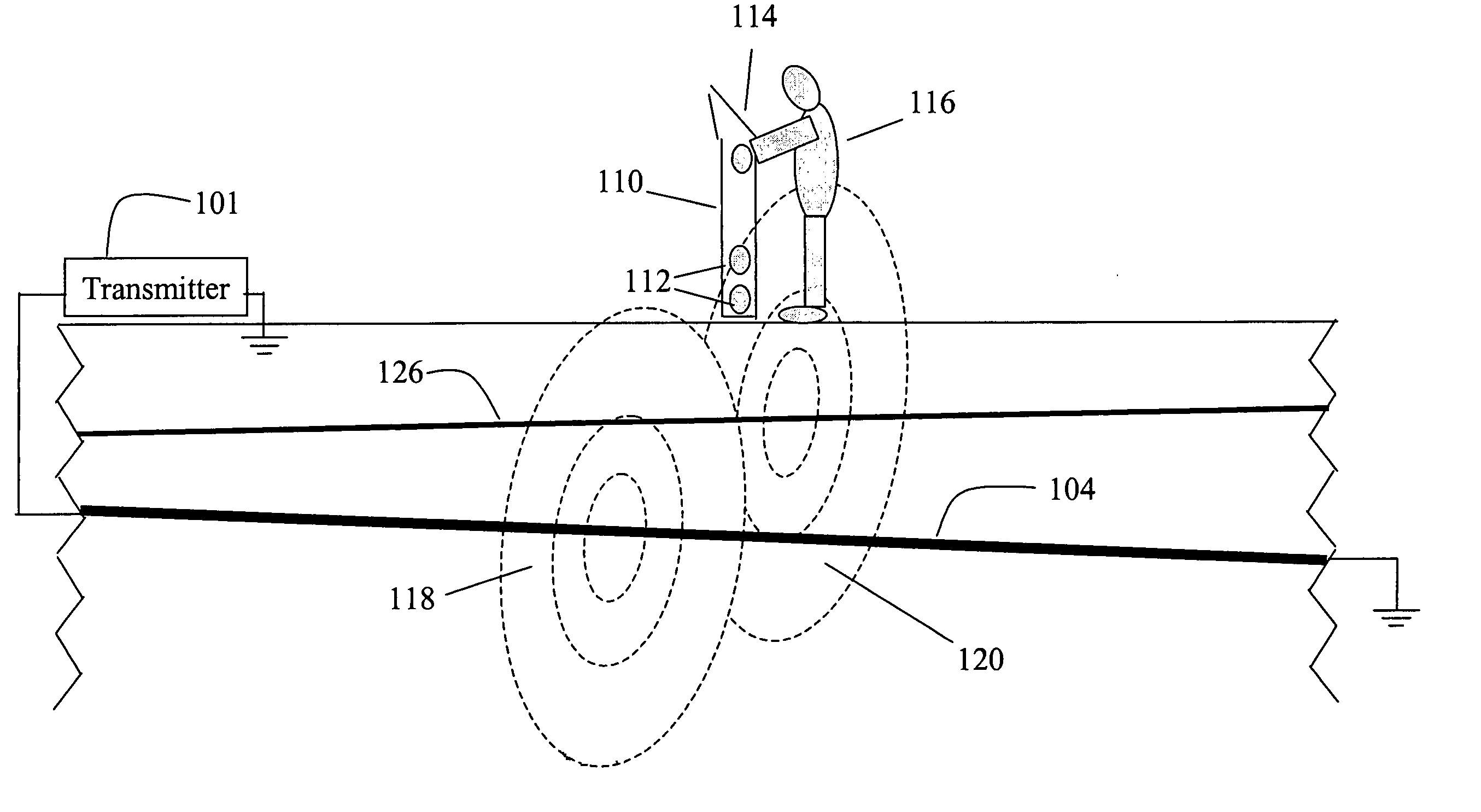
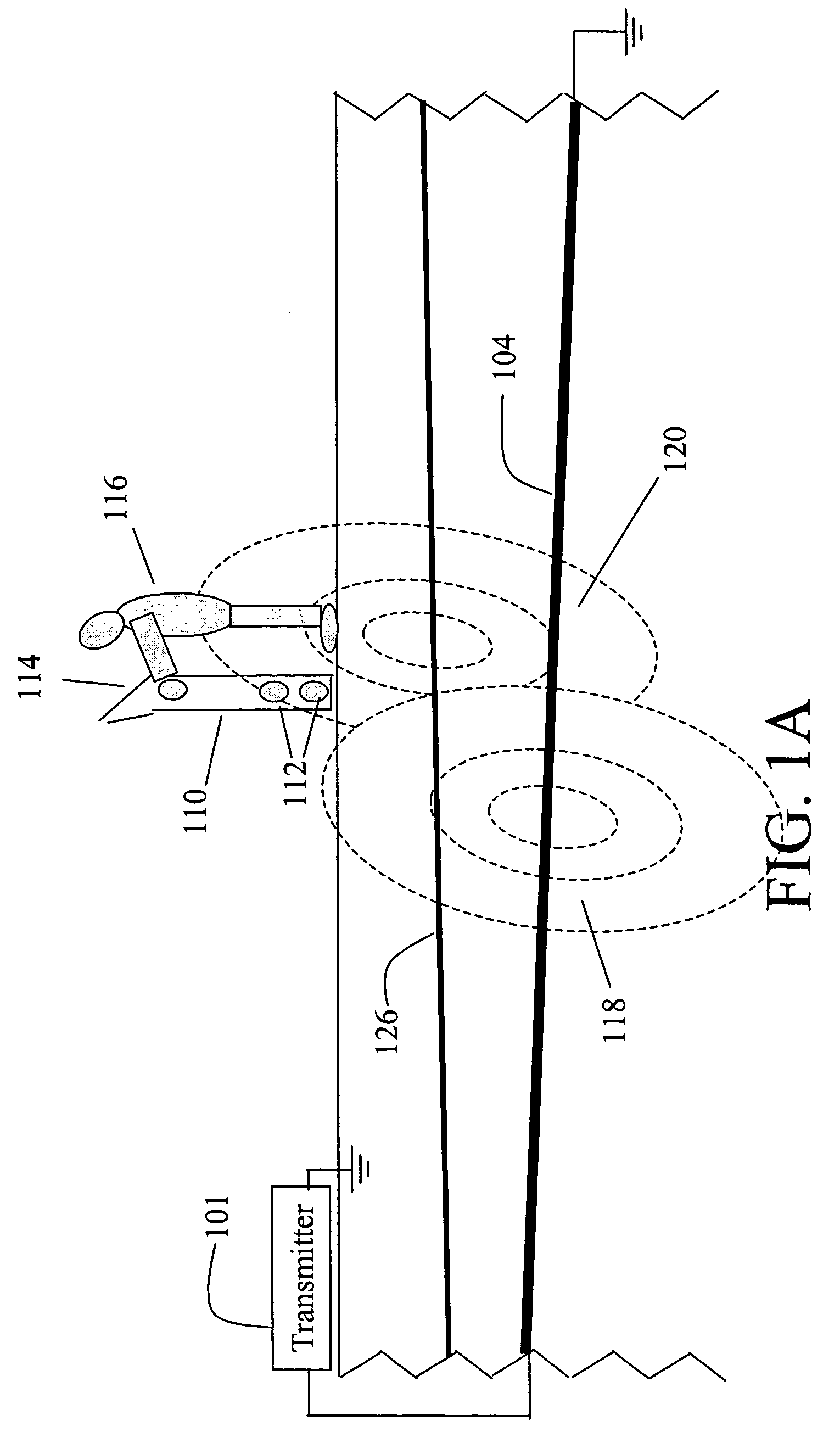
[0026]FIG. 1A illustrates a line location environment with a line locator. The line locator includes locator 110 and transmitter 101. Locator 110 can include an embodiment of receiver according to the present invention or may be a conventional locator. An example of a mostly digital implementation of a receiver 110 is described in U.S. application Ser. No. 10 / 622,376, “Method and Apparatus for Digital Detection of Electromagnetic Signal Strength and Signal Direction in Metallic Pipes and Cables,” by James W. Waite and Johan D. Overby (the '376 application), which is assigned to the same assignee as is the present invention and herein incorporated by reference in its entirety.

[0027]Locator 110 is operated by operator 116 in order to locate target conductor 104. Target conductor 104 is directly coupled to transmitter 101. In many systems, transmitter 101 couples a current signal onto conductor 104. As discussed above, the current signal has a frequency at the active locate frequency, ...


PUM


Abstract

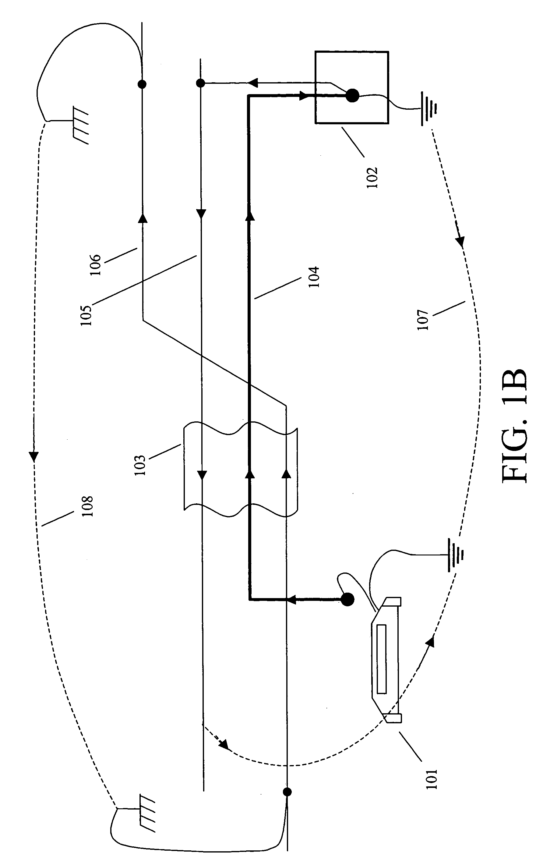
When cables run side by side over a longer distance, an alternating-current signal used for cable location can couple or ‘bleedover’ to neighboring cables. The coupled current flowing in the neighboring cable creates field distortion and makes position determination of the targeted cable difficult. The resulting magnetic field of both (or more) cables has a non-circular shape and is commonly known as a distorted field. Established methods for finding the position of the cable under investigation lead to inaccuracies or even wrong locates. The method described herein eliminates the field distortion that is due to the coupled cables by demodulating a phase reference signal placed on the cable by a transmitter into two signal strength constituents. The inphase signal represents the field strength of the targeted conductor and is substantially free of field distortion. The other quadrature signal contains the component of the field associated with distortion.

Description

BACKGROUND[0001]1. Field of the Invention[0002]The present invention relates to detection of electromagnetic signals from targeted hidden conductors and, in particular, to the decoupling of interference signals in detected signals from the targeted hidden conductors that result from bleedover of the transmitted signal to adjacent non-targeted conductors.[0003]2. Discussion of Related Art[0004]Underground pipe and cable locators (sometimes termed line locators) have existed for many years and are well known. Line locator systems typically include a mobile receiver and a transmitter. The transmitter is coupled to a target conductor, either by direct electrical connection or through induction, to provide a current signal on the target conductor. The receiver detects and processes signals resulting from the electromagnetic field generated at the target conductor as a result of the current signal, which can be a continuous wave sinusoidal signal provided to the target conductor by the tr...

Claims


Application Information

Patent Timeline
Patent Type & Authority Patents(United States)
IPC IPC(8): G01R19/00G01V3/08
CPCG01V3/088
Inventor SCHLAPP, HUBERTOVERBY, JOHAN D.
Owner BUSAN TRANSPORTATION CORPORATION
Learn More