Picture synthesizing apparatus

Active Publication Date: 2006-06-06
PANASONIC CORP
View PDF12 Cites 35 Cited by
  • Summary
  • Abstract
  • Description
  • Claims
  • Application Information

AI Technical Summary

Benefits of technology

[0016]By the constitution, the image obtained by the image pickup means or the synthesized image can be displayed in the display means, and provided to the operator, so that the operator can easily grasp

Problems solved by technology

In this case, there is a problem that a distance to a surrounding solid object is w

Method used


Image

  • Picture synthesizing apparatus
  • Picture synthesizing apparatus
  • Picture synthesizing apparatus

Examples


first embodiment

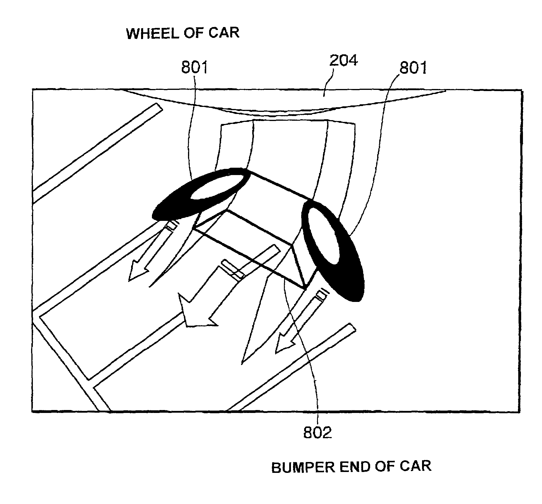
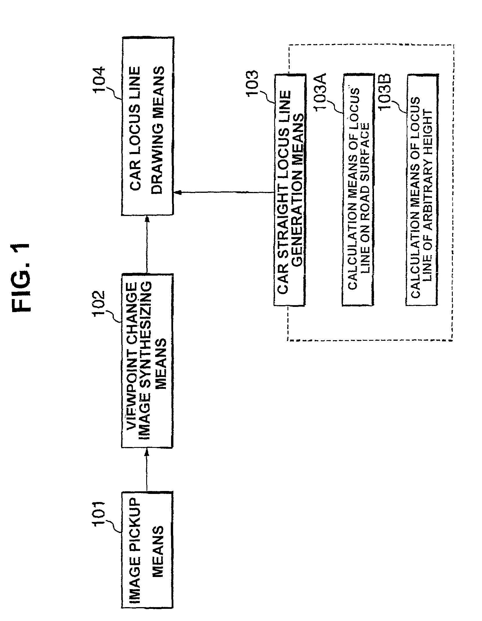
[0049]FIG. 1 is a block diagram showing a constitution of a picture synthesizing apparatus according to a first embodiment. The picture synthesizing apparatus is constituted of image pickup means 101 disposed in a car, viewpoint change image synthesizing means 102, car straight locus line generation means 103, and car locus line drawing means 104.

[0050]The image pickup means 101 is constituted of one or more cameras disposed in a rear or side part of the car, and turns to the rear of the car. The viewpoint change image synthesizing means 102 inputs one or more images obtained by the image pickup means 101, and outputs a synthesized image viewed from a virtual viewpoint. The car straight locus line generation means 103 inputs a size and shape of the car, camera parameter for changing the viewpoint, and image pickup situation of the image pickup means 101, and outputs a locus line in a case in which the car runs straight backwards. The car straight locus line generation means 103 incl...

second embodiment

[0069]FIG. 7 is a block diagram showing the constitution of the picture synthesizing apparatus according to a second embodiment. In FIG. 2, the same constituting elements as those of FIG. 1 or the corresponding constituting elements are denoted with the same reference numerals as those of FIG. 1.

[0070]The picture synthesizing apparatus is constituted by disposing car steering angle corresponding locus line generation means 502 instead of the car straight locus line generation means 103, adding steering angle information output means 501, and inputting an output of the means to the car steering angle corresponding locus line generation means 502 in the picture synthesizing apparatus of FIG. 1. Other constituting elements have the same constitution as that of the apparatus of FIG. 1.

[0071]The steering angle information output means 501 is a device for outputting a steering wheel angle of the car. The car steering angle corresponding locus line generation means 502 is a device for inpu...

third embodiment

[0078]FIG. 12 is a block diagram showing the constitution of the picture synthesizing apparatus according to a third embodiment. In FIG. 12, the same constituting elements as those of FIG. 7 or the corresponding constituting elements are denoted with the same reference numerals as those of FIG. 7.

[0079]The picture synthesizing apparatus is constituted by adding obstacle collision prediction means 901 and obstacle collision emphasis display means 902 to the apparatus of FIG. 7, and other constituting elements have a constitution similar to the constitution of the apparatus of FIG. 7.

[0080]The obstacle collision prediction means 901 is a device for detecting obstacles such as a car present around the car. Moreover, the car locus line drawing means 104 has a function of not drawing the subsequent locus line, when the position of the obstacle detected by the obstacle collision prediction means 901 is judged to collide against the locus line of the car. The obstacle collision emphasis di...


PUM


Abstract

There is disclosed a picture synthesizing apparatus for superimposing an auxiliary image upon an image converted as if the image were photographed with a virtual viewpoint, displaying the image in a monitor, and providing the image such that an approach to a surrounding solid object can easily be predicted from the monitor image. The picture synthesizing apparatus includes: an image pickup unit 101 disposed in a car; a viewpoint change image synthesizing unit 102 for changing a viewpoint of the image obtained by the image pickup unit 101 and synthesizing the image; a car straight locus line generation unit 103 for generating a locus line at an arbitrary height of the car, when the car linearly advances; and a car locus line drawing unit 104 for drawing the locus line generated by the car straight locus line generation unit 103 on the image synthesized by the viewpoint change image synthesizing unit 102.

Description

BACKGROUND OF THE INVENTION[0001]1. Field of the Invention[0002]The present invention relates to a picture synthesizing apparatus, particularly to a picture synthesizing apparatus preferable for use in an apparatus which changes a viewpoint, converts images obtained by a plurality of image pickup devices disposed in a car to images from a virtual viewpoint, synthesizes the images, provides an image around the car to a driver, and helps the driver to drive the car, for example, at a parking time.[0003]2. Description of the Related Art[0004]As a conventional image display apparatus, an apparatus has been known which changes a viewpoint of an image actually photographed by a camera, converts the image as if the image were photographed from a virtual viewpoint, and displays the image in a monitor as disclosed in “the Principle of virtual Viewpoint Image Synthesis using a Road Surface Model” (the 7th ITS International Conference). Moreover, an apparatus described in Japanese Patent No. 2...

Claims


Application Information

Patent Timeline
IPC IPC(8): G06K9/00B60R21/00B60R1/00B60R11/02G06T1/00G06T3/00G06T19/00H04N7/18
CPCB60R1/00B62D15/0295H04N7/181B60R2300/301B60R2300/302B60R2300/305B60R2300/806B60R2300/8093Y02T10/84B60R2300/602H04N5/262B60R21/00
Inventor IIDA, RYOSUKEMIZUSAWA, KAZUFUMIMIWA, MICHIO
Owner PANASONIC CORP
Why Eureka
Try Eureka