Corner flashing for windows and the like

a technology for windows and corners, applied in the direction of window/door frames, snow traps, sills/thresholds, etc., can solve the problems of window leaking water to the sill, damage to the wall, and providing a waterproof barrier

Active Publication Date: 2006-06-13
ALLEN L ROSS
View PDF43 Cites 35 Cited by
  • Summary
  • Abstract
  • Description
  • Claims
  • Application Information

AI Technical Summary

Benefits of technology

[0005]The present invention provides a corner flashing and method for use in installing a portal, such as a window, in an opening in a wall. The flashing defines channels for directing water outward of the wall, thereby restricting the passage of water inward through the wall around the portal.

Problems solved by technology

The barrier material forms a moisture barrier extending over the outer surface, but due to the cuts in the barrier material does not normally provide a waterproof barrier on the inner surfaces of the rough opening.
However, in some cases, the window can leak water to the sill.
Thus, the water can flow into the wall, i.e., between the inner and outer surfaces of the wall, causing damage to the wall.

Method used


Image

  • Corner flashing for windows and the like
  • Corner flashing for windows and the like
  • Corner flashing for windows and the like

Examples


Embodiment Construction

[0018]The present invention now will be described more fully hereinafter with reference to the accompanying drawings, in which preferred embodiments of the invention are shown. This invention may, however, be embodied in many different forms and should not be construed as limited to the embodiments set forth herein; rather, these embodiments are provided so that this disclosure will be thorough and complete, and will fully convey the scope of the invention to those skilled in the art. Like numbers refer to like elements throughout.

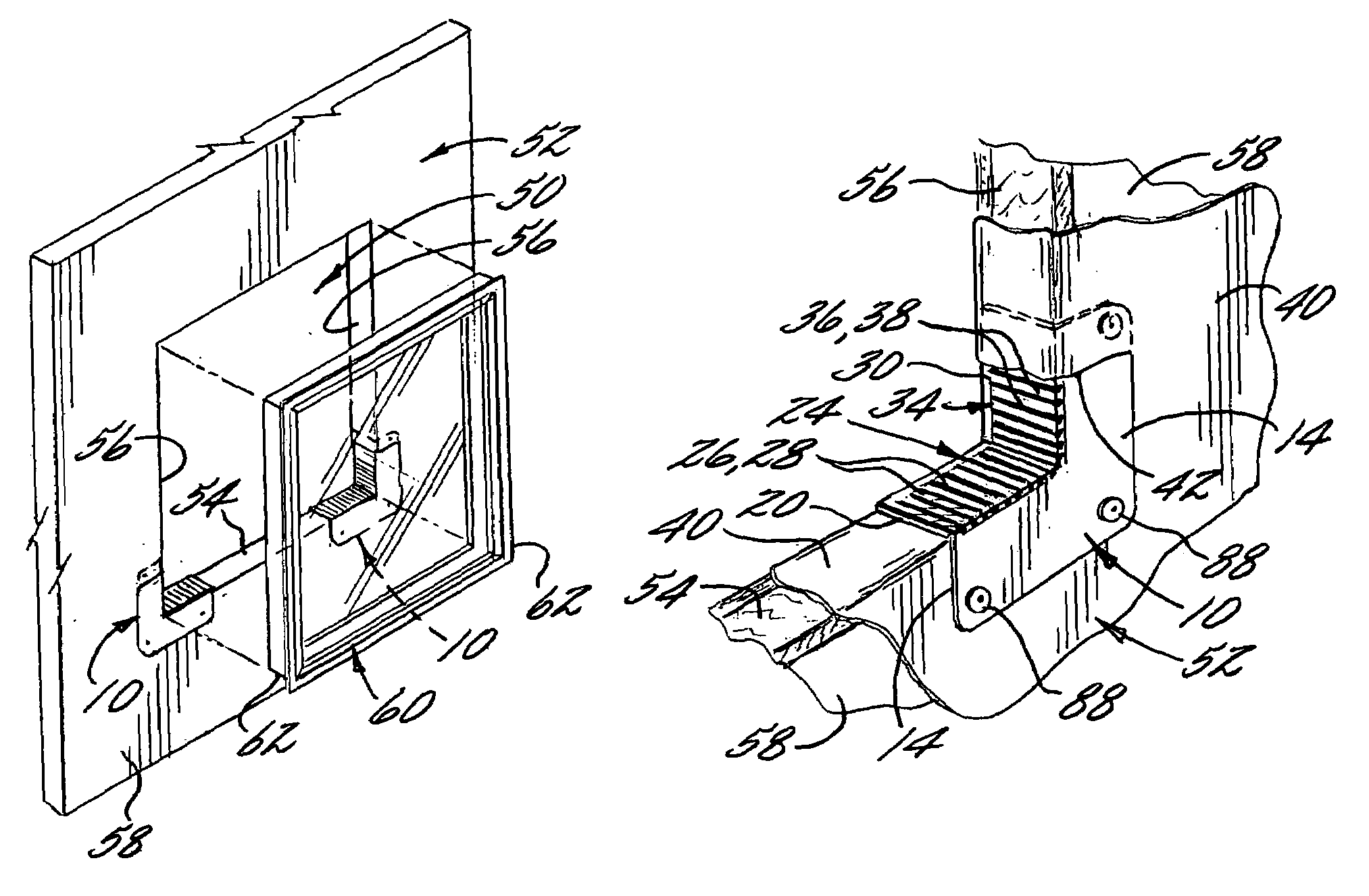
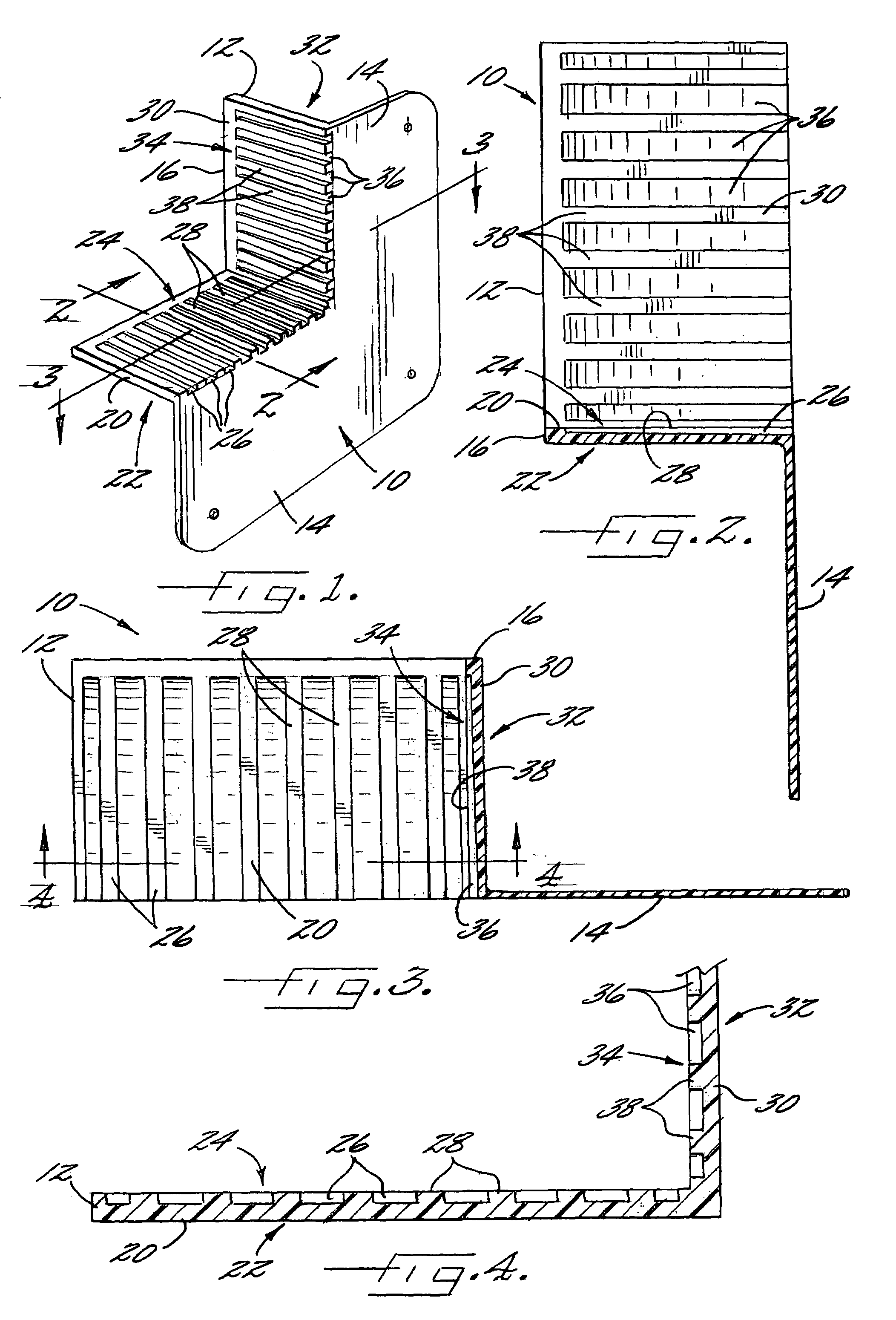
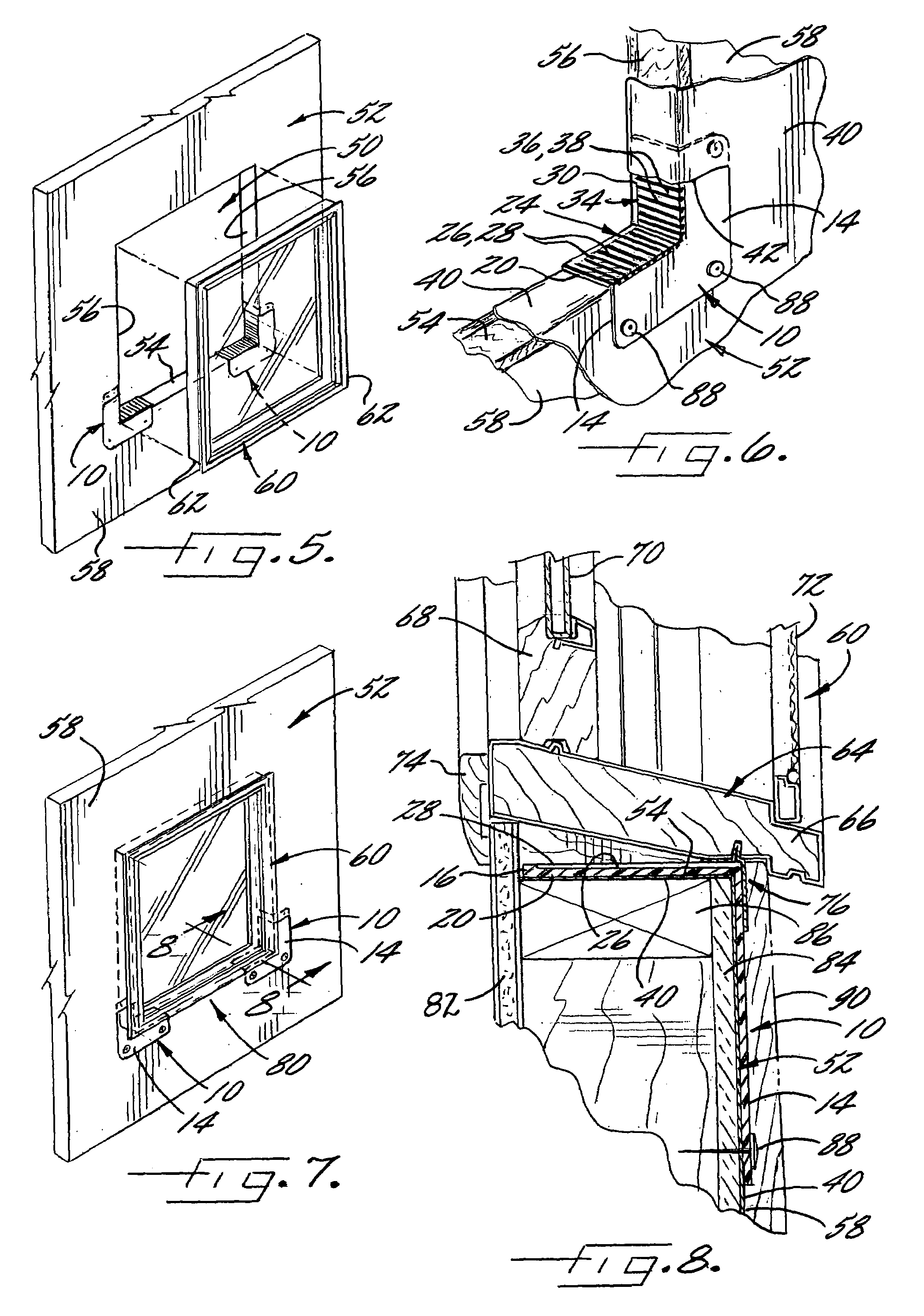
[0019]Referring to the drawings and, in particular, to FIG. 1, there is shown a corner flashing 10 according to one embodiment of the present invention. The corner flashing 10 is structured to be installed in a wall opening 50 in connection with the installation of a window 60 (FIG. 5) or other portal in the opening 50 so that the flashing 10 directs water out of the opening 50, e.g., to the outside of a building. Accordingly, the flashing 10 is preferably...


PUM


Abstract

A flashing and method for installing a window or other portal in a wall opening is provided. The flashing includes a base member with first and second portions that are angled so that an outer surface of the first portion can be disposed against a sill of the opening and an outer surface of the second portion can be disposed against one of the jambs of the opening. A front face plate of the flashing extends perpendicularly from the first and second portions of the base member, and a plurality of channels in the base member are structured to direct water toward and through the front face plate.

Description

FIELD OF THE INVENTION[0001]This invention relates to the installation of windows or other building members and, more particularly, relates to a flashing for directing water and preventing leakage of the water at a window or other portal.BACKGROUND OF THE INVENTION[0002]During a typical installation of a window in a building, a rough opening is first prepared in a wall of the building for receiving the window. The rough opening is defined by two jambs that extend vertically from a head at the top of the rough opening to a sill at the bottom of the opening. A weather resistant barrier material, such as a thin sheet of waterproof paper or plastic can be disposed over the outer surface of the wall, and the barrier material is cut at the rough opening and folded into the opening. The barrier material forms a moisture barrier extending over the outer surface, but due to the cuts in the barrier material does not normally provide a waterproof barrier on the inner surfaces of the rough open...

Claims


Application Information

Patent Timeline
Patent Type & Authority Patents(United States)
IPC IPC(8): E04B1/70E04F17/00E06B1/62E06B1/70
CPCE06B1/62E06B1/702E06B2001/628
Inventor ALLEN, L. ROSS
Owner ALLEN L ROSS
Why Eureka
Try Eureka