Advanced particulate matter control apparatus and methods

a technology of particulate matter and control apparatus, which is applied in the field of collecting particulate materials, can solve the problems of inability to collect the waste water from such large pore size filters, exhibit a substantial pressure drop, and associated rapid increase in back pressure, and achieve the effect of limiting the pressure drop across the conductive filter membran

Active Publication Date: 2011-08-11
ENERGY & ENVIRONMENTAL RES CENT FOUNDATIO
View PDF0 Cites 12 Cited by
  • Summary
  • Abstract
  • Description
  • Claims
  • Application Information

AI Technical Summary

Benefits of technology

[0007]The present invention discloses a collection apparatus having an electrostatic precipitator combined with a porous conductive filter membrane, both of which can be optionally packaged into a compact unit. Electrostatic precipitation can be used to both pre-collect particulate matter and to drive particulate matter to the filter membrane surface. The pre-collection can be employed to effectively limit the pressure drop across the conductive filter membrane and collect filter cake over time. The conductive filter membrane can also serve as a grounded collection plate and double in function as a porous media filter, thereby limiting passage of solid and aerosolized particulate matter while permitting gas flow with a low pressure drop across the collection apparatus.

Problems solved by technology

However, such filters exhibit a substantial pressure drop for gas flowing therethrough with an associated rapid increase in back pressure as the particles collect on the filter surface.
Alternatively, a decrease in pressure drop across the filter can be obtained by employing increased pore sizes, however the collection efficiency of such larger pore size filters is not acceptable.
As such, a balance between pore size, need for low pressure drop and collection efficiency is a theoretical limitation for all filters that rely on primary filtration collection mechanisms.

Method used


Image

  • Advanced particulate matter control apparatus and methods
  • Advanced particulate matter control apparatus and methods
  • Advanced particulate matter control apparatus and methods

Examples


Embodiment Construction

n;

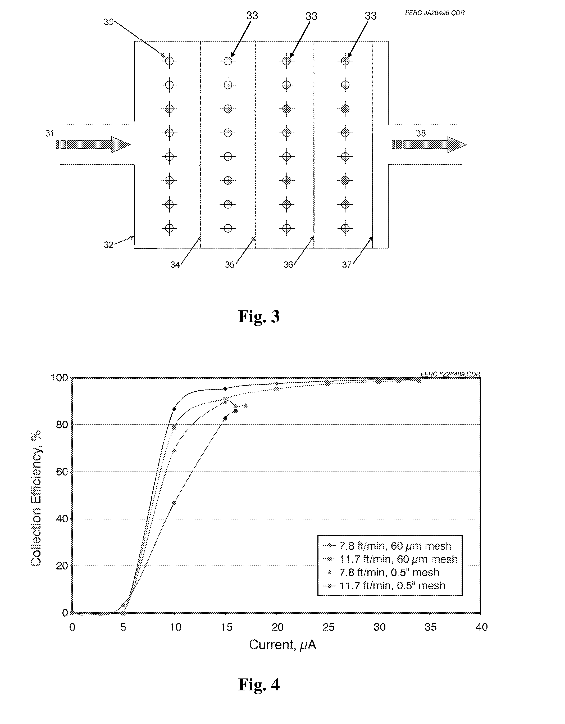
[0018]FIG. 4 is a plot of collection efficiency vs. current for an embodiment of the present invention;

[0019]FIG. 5 is a plot of collection efficiency vs. particle diameter for an embodiment of the present invention;

[0020]FIG. 6 is a top view of a hybrid electrostatic precipitator / filter membrane according to an embodiment of the present invention;

[0021]FIG. 7 is a side view of a hybrid electrostatic precipitator / filter membrane shown in FIG. 6;

[0022]FIG. 8 is a plot of particle concentration collected vs. particle diameter for an embodiment of the present invention;

[0023]FIG. 9 is a plot of particle mass concentration vs. operating time for tests according to an embodiment of the present invention;

[0024]FIG. 10 is a plot of filter drag for a hybrid electrostatic precipitator / filter membrane according to an embodiment of the present invention;

[0025]FIG. 11A is a schematic illustration of a filtration mechanism for a prior art filter; and

[0026]FIG. 11B is a schematic illustration o...


PUM

PropertyMeasurementUnit
pore diameteraaaaaaaaaa
temperatureaaaaaaaaaa

Abstract

Apparatus and methods for collection and removal of particulate matter, including fine particulate matter, from a gas stream, comprising a unique combination of high collection efficiency and ultralow pressure drop across the filter. The apparatus and method utilize simultaneous electrostatic precipitation and membrane filtration of a particular pore size, wherein electrostatic collection and filtration occur on the same surface.

Description

CROSS-REFERENCE TO RELATED APPLICATIONS[0001]This application claims the benefit under 35 U.S.C Section 119(e) of U.S. Provisional Patent Application No. 61 / 303,493 entitled “Advanced Particulate Matter Control Apparatus and Methods,” filed Feb. 11, 2010, the disclosure of which is hereby incorporated herein by reference.STATEMENT REGARDING FEDERALLY SPONSORED RESEARCH OR DEVELOPMENT[0002]This invention was made with U.S. Government support under the U.S. Department of Energy Cooperative Agreement No. DE-FC26-98FT40320, Base Cooperative Agreement, Task 2.5—Emissions Control for Diesel Systems. The U.S. Government has certain rights in this invention.FIELD OF THE INVENTION[0003]The present invention relates to the collection of particulate materials, and in particular, the present invention relates to an apparatus and process for the collection of particles entrained in a gas stream.BACKGROUND OF THE INVENTION[0004]The control of fine particles by filtration alone depends on capturin...

Claims


Application Information

Patent Timeline
Patent Type & Authority Applications(United States)
IPC IPC(8): B03C3/34B03C3/74B03C3/38B01D53/38
CPCB01D53/22Y10S55/30B01D65/02B01D69/02B01D69/145B01D2311/2603B01D2313/08B01D2313/345B01D2321/04B01D2321/18B01D2321/30B01D2321/32B01D2325/02B01D2325/10B01D2325/26B03C3/011B03C3/155B03C2201/08B01D63/06
Inventor MILLER, STANLEY J.ZHUANG, YEALMLIE, JAY C.
Owner ENERGY & ENVIRONMENTAL RES CENT FOUNDATIO
Why Eureka
Try Eureka