Multi-probe pressure transient analysis for determination of horizontal permeability, anisotropy and skin in an earth formation

a technology of anisotropy and skin, applied in earth drilling, survey, well accessories, etc., can solve the problems of insufficient ascertaining the horizontal and vertical components of permeability, affecting the ability of downhole formation to produce hydrocarbons, and not being determined or compensated by boreholes traversing earth formations

Active Publication Date: 2006-06-13
HALLIBURTON ENERGY SERVICES INC
View PDF14 Cites 23 Cited by
  • Summary
  • Abstract
  • Description
  • Claims
  • Application Information

AI Technical Summary

Problems solved by technology

Thus, using only a single probe, while giving the ability to determine the permeability generally, is not sufficient to ascertain the horizontal and vertical components of the permeability.
However, there are aspects of a borehole traversing an earth formation that are not determined or compensated for in devices such as those described in the U.S. Pat. No. 5,247,830.
Secondly, the circulation of drilling mud through the annular region carries cuttings away from the drill bit.
The rather violent process of drilling through an earth formation, in combination with the drilling mud present during the process, affects the downhole formation's ability to produce hydrocarbons.
In particular, the act of drilling tends to damage, even if slightly, the formation immediately adjacent to the borehole wall.
This damage may affect the permeability of the formation in this location.
Further, the presence of the drilling mud at pressures greater than the formation results in invasion of the mud into the formation.
This too tends to affect the permeability of the formation at locations adjacent to the borehole.
While related art devices have advanced in their ability to determine both the horizontal and vertical components of the permeability in downhole formation, they are not capable of accounting for the affects of the formation damage and invasion of the drilling fluid near the borehole wall—which combination of factors is collectively known in the industry as “skin.” The effect of the skin on the measured permeability may be as high as an order of magnitude, thus contributing substantially to error in related art permeability determinations, as they do not take skin into account.
Other factors too introduce error into related art determinations of permeability anisotropy, like compressibility of formation fluids and dip angle of the formation.
Related art permeability testing devices do not compensate for the dip angle.

Method used


Image

  • Multi-probe pressure transient analysis for determination of horizontal permeability, anisotropy and skin in an earth formation
  • Multi-probe pressure transient analysis for determination of horizontal permeability, anisotropy and skin in an earth formation
  • Multi-probe pressure transient analysis for determination of horizontal permeability, anisotropy and skin in an earth formation

Examples


Embodiment Construction

[0025]This application is directly related to the Society of Petroleum Engineers Conference Paper SPE 64650 titled “Advanced Dual Probe Formation Tester with Transient, Harmonic, and Pulsed Time-Delay Testing Methods Determines Permeability, Skin and Anisotropy,” which is incorporated herein by reference as if reproduced in full below. This application is also related to the Society of Petroleum Engineers Paper SPE 62919 titled “Advanced Permeability and Anisotropy Measurements While Testing and Sampling in Real-Time Using a Dual Probe Formation Tester,” which is also incorporated herein by reference as if reproduced in full below.

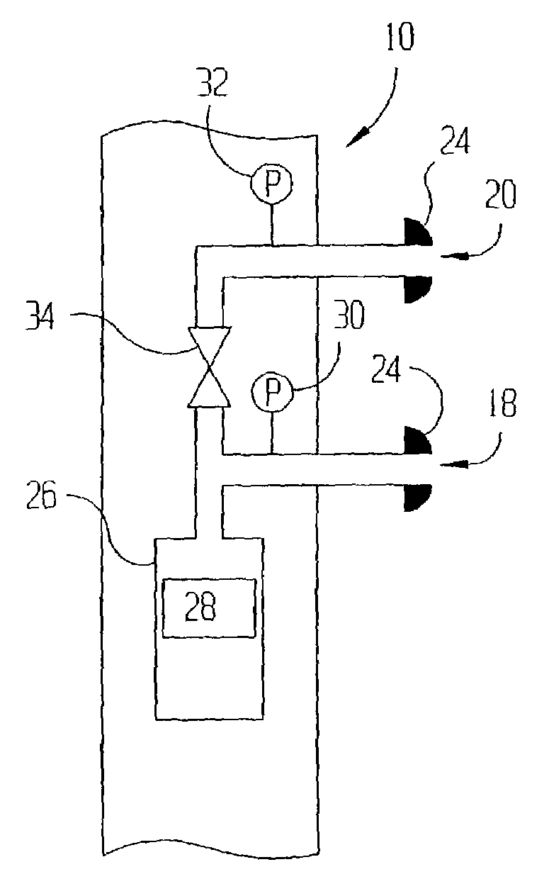
[0026]FIG. 1 shows a wireline formation tester 10 constructed in accordance with the preferred embodiments. In particular, the wireline formation tester is preferably disposed within a borehole 12 traversing earth formations. The wireline formation tester 10 is preferably suspended by an armored multi-conductor cable 14, which not only supports the formati...


PUM


Abstract

The specification discloses a downhole tool that determines hydraulic permeability of a downhole formation taking into account one or both of the dip angle of the borehole relative to the formation, and damage to the borehole wall and invasion of borehole fluid—collectively referred to as skin.

Description

CROSS-REFERENCE TO RELATED APPLICATIONS[0001]This application claims the benefit of Provisional Application Ser. No. 60 / 325,903, which is incorporated herein by reference as if reproduced in full below.STATEMENT REGARDING FEDERALLY SPONSORED RESEARCH OR DEVELOPMENT[0002]Not applicable.BACKGROUND OF THE INVENTION[0003]1. Field of the Invention[0004]The preferred embodiments of the present invention generally relate to determining hydraulic permeability of earth formations traversed by a borehole. More particularly, the preferred embodiments are directed to determining permeability anisotropy of the earth formations. More particularly still, the preferred embodiments are directed to determining the hydraulic permeability, permeability anisotropy and skin using an analytic model that considers the storage effect downhole, as well as the dip angle of the formation relative to the borehole.[0005]2. Description of the Related Art[0006]It is well known that some earth formations exhibit an...

Claims


Application Information

Patent Timeline
Patent Type & Authority Patents(United States)
IPC IPC(8): E21B49/00E21B49/10
CPCE21B49/10E21B49/008
Inventor PROETT, MARK A.CHIN, WILSON C.
Owner HALLIBURTON ENERGY SERVICES INC
Why Eureka
Try Eureka