Gain and signal level adjustments of cascaded optical amplifiers

Inactive Publication Date: 2006-06-13
FUJITSU LTD
View PDF20 Cites 18 Cited by
  • Summary
  • Abstract
  • Description
  • Claims
  • Application Information

AI Technical Summary

Benefits of technology

The technical effect of this patent is that it provides an optical amplifier system without requiring a powerful laser for its operation.

Problems solved by technology

The technical problem addressed in this patent text is the limited transmission distance in optical communication systems due to the wavelength characteristic of gain in optical amplifiers. The solution proposed is an optical amplification device that maintains the wavelength characteristic of gain constant and obtains a wide input dynamic range by using automatic gain control and automatic output level control. However, this device requires a high-power pumping light source for the first optical amplifier to ensure a required input dynamic range.

Method used


Image

  • Gain and signal level adjustments of cascaded optical amplifiers
  • Gain and signal level adjustments of cascaded optical amplifiers
  • Gain and signal level adjustments of cascaded optical amplifiers

Examples


Embodiment Construction

[0053]Reference will now be made in detail to the present preferred embodiments of the present invention, examples of which are illustrated in the accompanying drawings, wherein like reference numerals refer to like elements throughout.

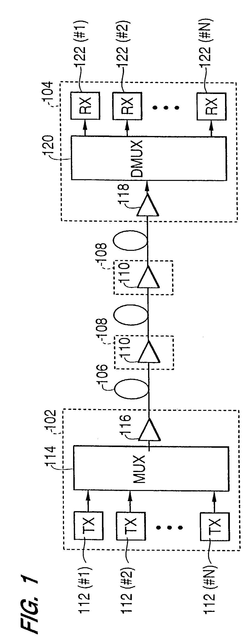
[0054]FIG. 1 is a diagram illustrating an optical fiber communication system, according to an embodiment of the present invention. Referring now to FIG. 1, the system includes a first terminal station 102, a second terminal station 104, an optical fiber transmission line 106 connecting terminal stations 102 and 104, and a plurality of optical repeaters 108 arranged along optical fiber transmission line 106. Each optical repeater 108 includes an optical amplifier 110 optically connected to optical fiber transmission line 106. Although FIG. 1 shows two optical repeaters 108, more than two optical repeaters can be used, depending on the system design parameters. Further, in some systems, a single optical repeater may be used.

[0055]First terminal station ...


PUM


Abstract

An optical amplification device which includes first and second optical amplifiers, and a controller. The first optical amplifier receives a light and amplifies the received light. The second optical amplifier receives the light amplified by the first optical amplifier, and amplifies the received light. When a level of the light received by the first optical amplifier changes by Δ, the controller controls a level of the light received by the second optical amplifier to change by approximately −Δ. In various embodiments, the controller causes the sum of the gains of the first and second optical amplifiers to be constant. In other embodiments, the optical amplification device includes first and second optical amplifier and a gain adjustor. The gain adjustor detects a deviation in gain of the first optical amplifier from a target gain, and adjusts the gain of the second optical amplifier to compensate for the detected deviation.

Description


Claims


Application Information

Patent Timeline
Owner FUJITSU LTD
Why Eureka
Try Eureka