
Methods and apparatus for implementing bi-directional signal interfaces using label switch paths

a label switch path and signal interface technology, applied in the field of communication systems, can solve the problems of inability to run such protocols over an mpls network, bandwidth waste, and inability to keep up with the latest increase in bandwidth

Inactive Publication Date: 2006-06-13
JUMIPER NETWORKS INC
View PDF6 Cites 140 Cited by
  • Summary
  • Abstract
  • Description
  • Claims
  • Application Information

AI Technical Summary

Benefits of technology

The present invention provides methods for implementing bi-directional signal interfaces, such as logical signal interfaces (LSIs), between label switching devices such as MPLS routers and switches. LSIs allow for the creation of a bi-directional path for communication between devices. The invention also includes the use of real labels to identify the LSI associated with a packet or message, as well as the use of label stacking and the replacement of existing ATM networks with LSIs. Additionally, the invention allows for the use of multicast routing protocols and the interconnection of virtual private networks (VPNs) using LSIs. The technical effects of the invention include improved network topology flexibility, improved reliability, and improved security.

Problems solved by technology

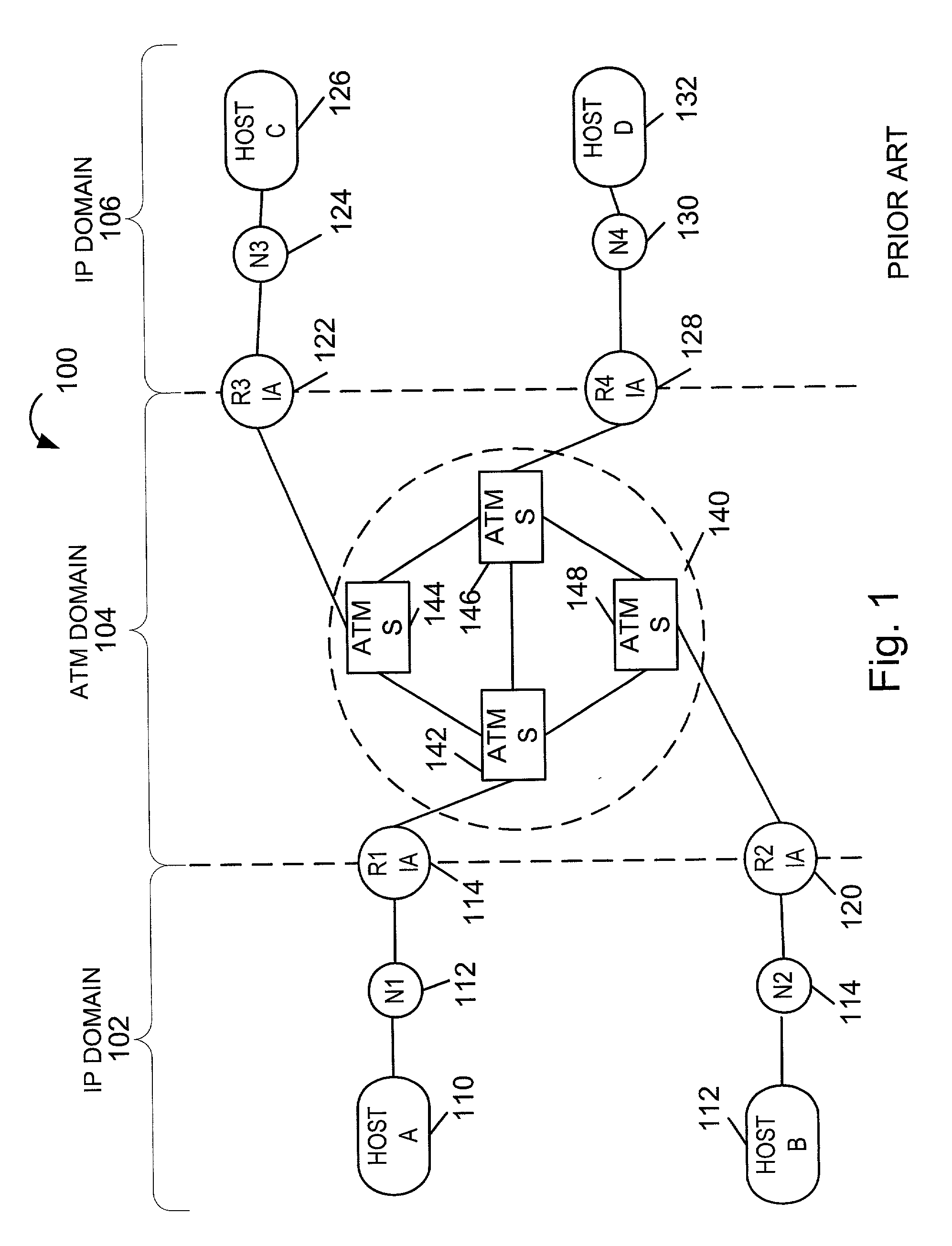
Unfortunately, ATM router interfaces have not kept pace with the latest increases in the bandwidth in optical cables used to carry Internet traffic.
In addition, since ATM uses fixed size cells to carry IP packets, ATM results in wasted bandwidth sometimes referred to as an ATM cell tax.
Unfortunately, various common signaling protocols were designed for bi-directional communications paths.
While such protocols are presently run over bi-directional ATM PVCs, the uni-directional nature of MPLS LSPs makes it difficult to run such protocols over an MPLS network.

Method used


Image

  • Methods and apparatus for implementing bi-directional signal interfaces using label switch paths
  • Methods and apparatus for implementing bi-directional signal interfaces using label switch paths
  • Methods and apparatus for implementing bi-directional signal interfaces using label switch paths

Examples


Embodiment Construction

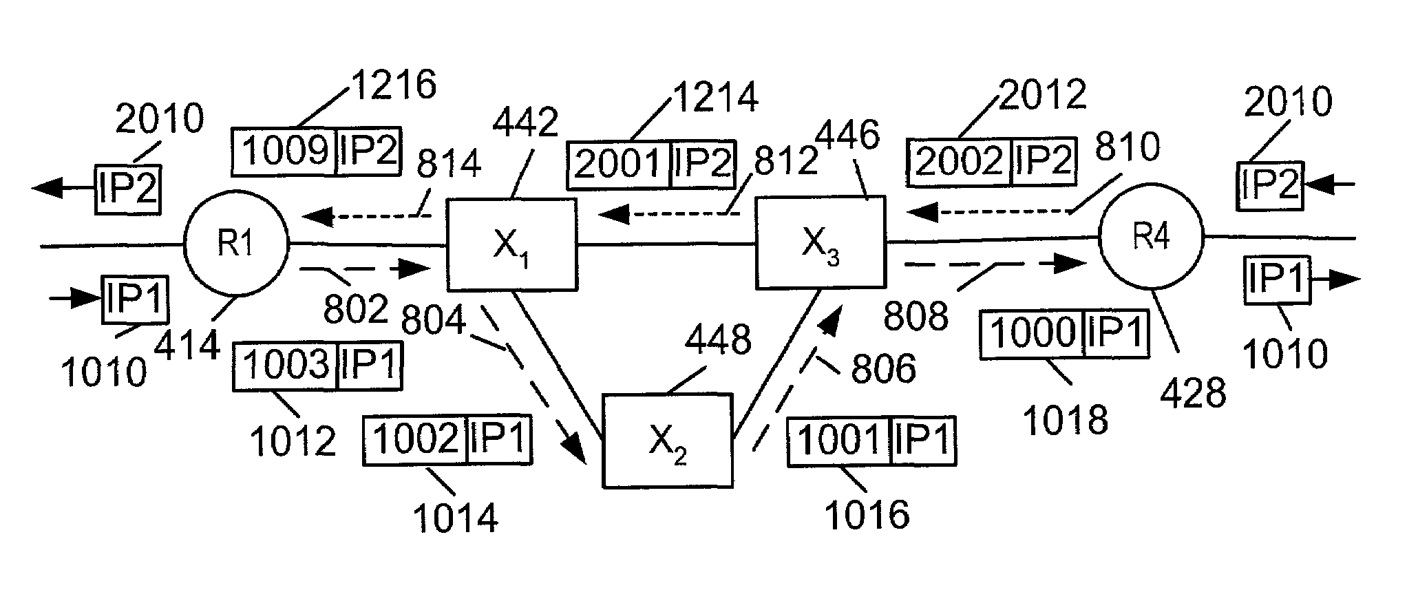
[0035]As discussed above, the present invention is directed to methods and apparatus for implementing bi-directional signal interfaces, e.g., logical signal interfaces (LSIs) in communications systems which use uni-directional label switched paths, (LSPs), e.g., MPLS networks.

[0036]In accordance with one feature of the present invention, two uni-directional LSPs, e.g., a transmit and a receive LSP, are bound together based on configuration information loaded into a network node, e.g., an MPLS router or switch. Each bound pair of uni-directional LSPs serves as a bi-directional LSI that can be used in a manner that is the same as, or similar to, the manner in which a PVC is used in an ATM network. Hereinafter, LSI will be used to refer to a pair of uni-directional LSPs which have been configured to serve as a bi-directional signal path.

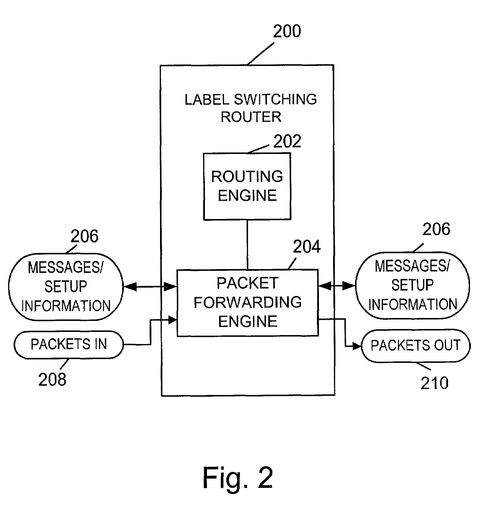
[0037]FIG. 2 illustrates an exemplary label switching router (LSR) 200 which can be used to support LSIs in accordance wit the present invention. The L...


PUM


Abstract

Methods and apparatus for implementing bi-directional logical signal interfaces (LSIs) in communications systems which use uni-directional label switched paths (LSPs), e.g., MPLS networks, are described. To implement an LSI, two uni-directional LSPs between the same end points, e.g., routers, and extending in opposite directions, are associated together. The association of LSPs may be done by setting LSI configuration information in the routers at both ends of an LSI. Each router at the end of an LSI serves as an egress router for one of the LSPs associated with the LSI and an ingress router for the other LSP associated with the LSI. To enable an egress router to determine which, if any, LSI a packet or message corresponds to, a real as opposed to a null label is used when sending packets over an LSI LSP to an LSI LSP egress router.

Description

RELATED APPLICATIONS[0001]This application claims the benefit of pending U.S. Provisional Patent Application Ser. No. 60 / 277,035 filed Mar. 19, 2001.FIELD OF THE INVENTION[0002]The present invention is directed to communications systems, and, more particularly, to methods and apparatus for implementing bi-directional communications using unidirectional label switched paths.BACKGROUND OF THE INVENTION[0003]Communications networks such as the Internet are used for transmitting information, e.g., digital data, from one device to another. Each communications network normally comprises a plurality of nodes. The nodes are implemented using, e.g., routers or switches, which are inter-connected by links over which data and control signals can pass. For ownership and administrative purposes, routers are frequently grouped together into individual networks referred to as autonomous systems (ASs). Individual networks, representing separate ASs, can be connected to each other to form a larger n...

Claims


Application Information

Patent Timeline
Patent Type & Authority Patents(United States)
IPC IPC(8): H04L12/56
CPCH04L12/18H04L45/50H04L45/16H04L45/04
Inventor SHETH, NISCHAL
Owner JUMIPER NETWORKS INC
Learn More