Piston engine with selectable firing order

a firing order and piston engine technology, applied in the direction of machines/engines, output power, non-mechanical valves, etc., can solve the problems of difficult, time-consuming, expensive and time-consuming engine modifications, and interfering with the connecting rod,

Inactive Publication Date: 2006-06-20
MOTOCZYSZ
View PDF2 Cites 11 Cited by
  • Summary
  • Abstract
  • Description
  • Claims
  • Application Information

AI Technical Summary

Problems solved by technology

The portion of the center shaft between the two webs is absent, or it would interfere with the connecting rod as the crankshaft turned.
Previously, in order to change a given engine with a particular crankshaft from one firing order to another, it was necessary to make a host of difficult, expensive, and time-consuming modifications to the engine.
In general, there are N2 / 2 possible firing orders for a given N-cylinder crankshaft, but only a limited number of these will be desirable; the others will suffer from balance or vibration problems.

Method used


Image

  • Piston engine with selectable firing order
  • Piston engine with selectable firing order
  • Piston engine with selectable firing order

Examples


Embodiment Construction

[0046]The invention will be understood more fully from the detailed description given below and from the accompanying drawings of embodiments of the invention which, however, should not be taken to limit the invention to the specific embodiments described, but are for explanation and understanding only.

[0047]FIG. 17 illustrates one embodiment of an a motor vehicle 100 which includes an improved multi-cylinder four-stroke engine 102 that permits an on-the-fly change between two or more firing orders. The motor vehicle includes a frame 110 to which the engine is coupled, and a driven wheel 112 which is powered by the engine.

[0048]The motor vehicle is illustrated as being a motorcycle. Although a racing motorcycle is one application in which the present invention may be especially advantageous, the invention is not limited to use in motorcycles, but can be used in essentially any vehicle which has a four-stroke engine.

[0049]A firing order selector switch 104 is triggered, causing a new...


PUM


Abstract

A multi-cylinder four-stroke internal combustion engine enabling a method for on-the-fly switching between two or more firing orders. Switching to the new firing order is done without requiring any tear-down of the engine such as to swap camshafts. Switching can be triggered by the rider, or it can be triggered automatically per conditions such as selected gear, RPM range, track location, velocity, and the like.

Description

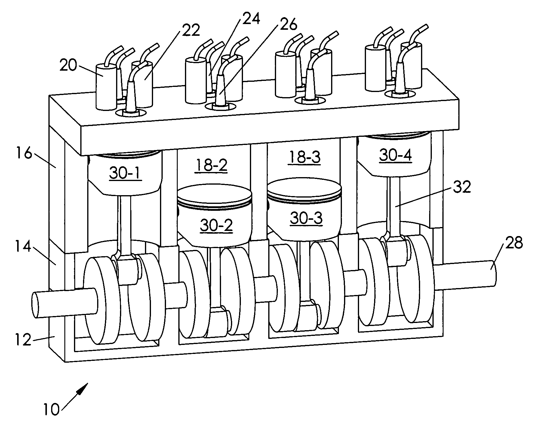
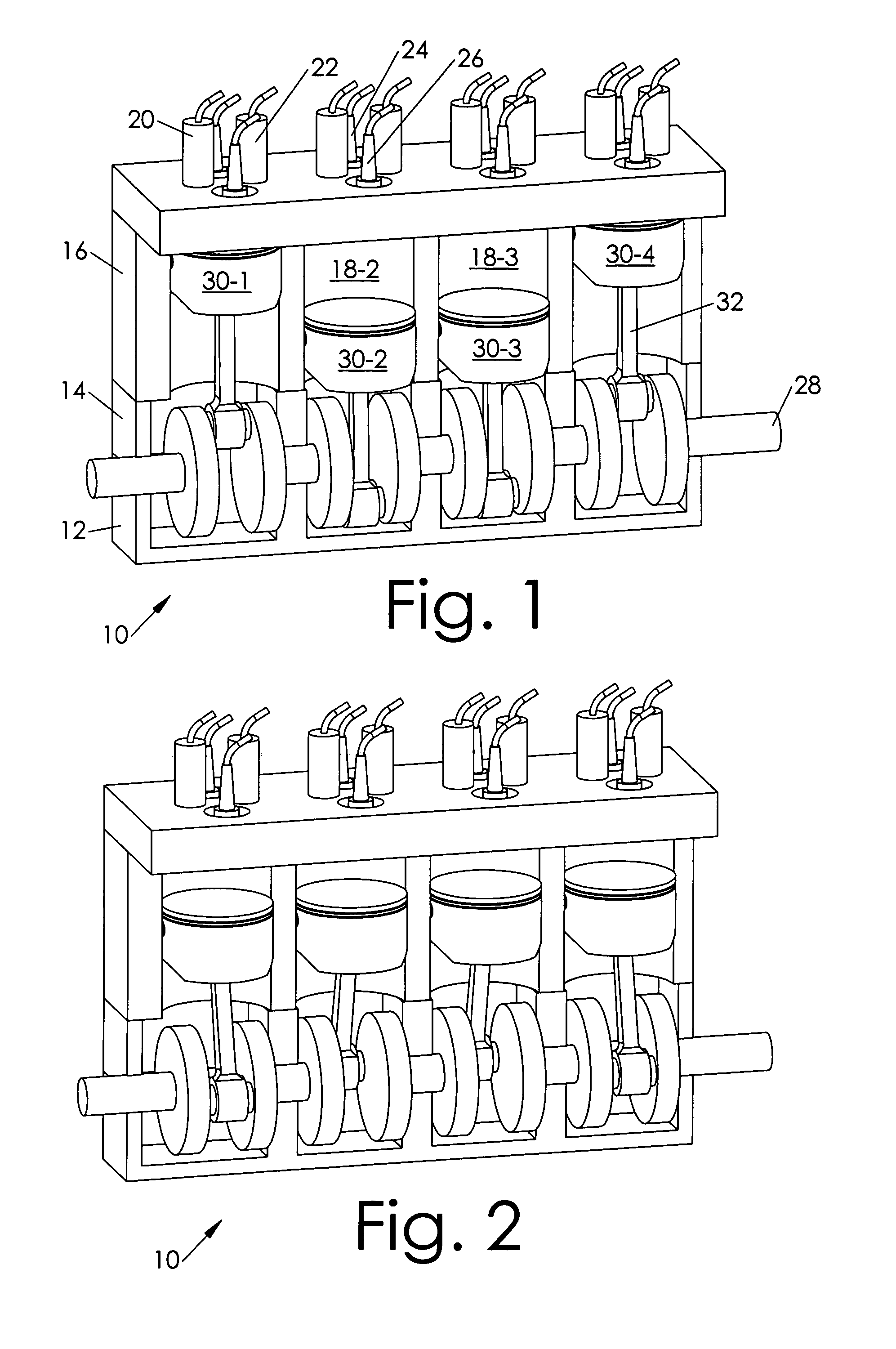
BACKGROUND OF THE INVENTION[0001]1. Technical Field of the Invention[0002]This invention relates generally to internal combustion engines, and more specifically to selectable firing order modes for such.[0003]2. Background Art[0004]The examiner is warned that the invention itself is not directly described until Page 8. The first six pages are a rather lengthy, but necessary, explanation of the prior art.[0005]FIG. 1 illustrates a four-cylinder engine 10 which, for purposes of illustrating the present invention, has been drastically simplified. Well-known features such as gears, bearings, intake tracts, exhaust manifolds, fluids, oil pumps, transmissions, gearboxes, counter balancer shafts, gaskets, water jackets and channels, and so forth have been omitted. Those of ordinary skill in the art of internal combustion engines would not be aided by their inclusion, as they are largely irrelevant to the invention.[0006]The four-stroke cycle is: intake, compression, power, exhaust. At the ...

Claims


Application Information

Patent Timeline
Patent Type & Authority Patents(United States)
IPC IPC(8): F02P1/00F01L9/10F01L9/16F01L9/20
CPCF02D13/0215F01L9/02F01L9/026Y02T10/18F01L9/04Y02T10/12F01L9/16F01L9/10F01L9/20
Inventor CALDERWOOD, RICHARD C.
Owner MOTOCZYSZ
Why Eureka
Try Eureka