

Top tensioned riser
a riser and top tension technology, applied in the direction of pipe laying and repair, mechanical equipment, borehole/well accessories, etc., can solve the problems of weight and cost increase significantly
- Summary
- Abstract
- Description
- Claims
- Application Information
AI Technical Summary
Benefits of technology
Problems solved by technology
Method used
Image

Examples
Embodiment Construction
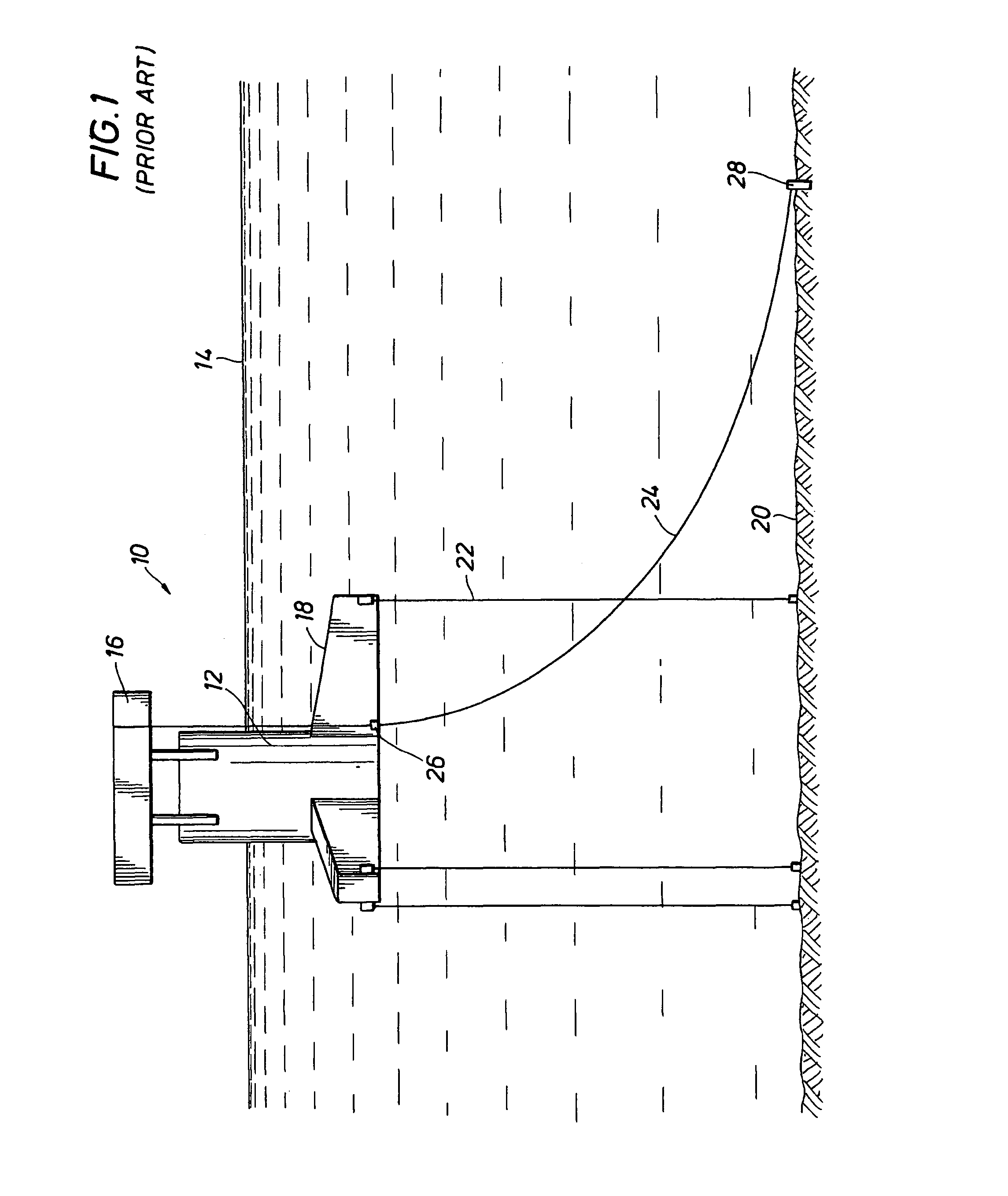
[0015]Referring first to FIG. 1, a typical mono-column TLP platform, generally identified by the reference numeral 10, is shown. The platform 10 includes a column or hull 12 projecting above the water surface 14 supporting one or more platform decks 16 thereon. Pontoons 18 extend radially outward from the bottom of the hull 12. The platform 10 is anchored to the seabottom 20 by tendons 22. A steel catenary riser 24 is supported at a porch 26 near the keel level of the platform hull 12. The catenary riser 24 takes a catenary path to the touchdown point 28 on the seabottom 20. The riser 24 may be hundreds or thousands of feet in length and is freely suspended between the support porch 26 and the touchdown point 28. Ocean currents could therefore move the riser 24 so that it interferes with the tendons 22 under certain environmental conditions.
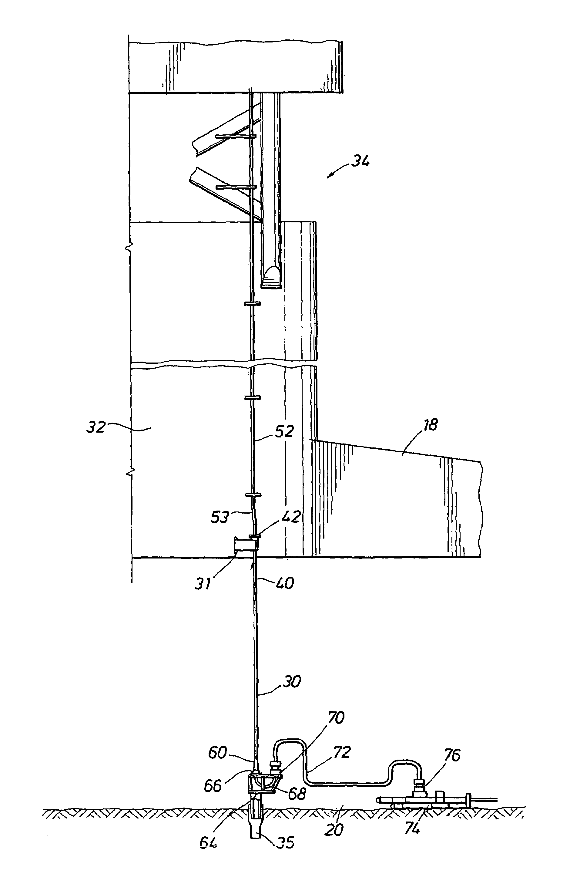
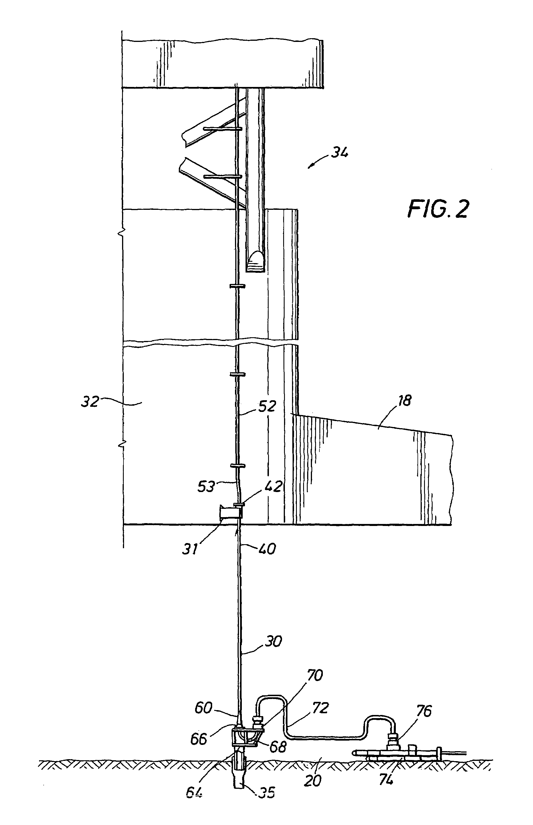
[0016]Referring now to FIG. 2, the top tensioned riser 30 of the present invention extends substantially vertically downward from a riser porch ...
PUM
 Abstract
Description
Claims
Application Information