
Method and apparatus for synthesizing or modifying a copy protection signal using a lowered signal level portion

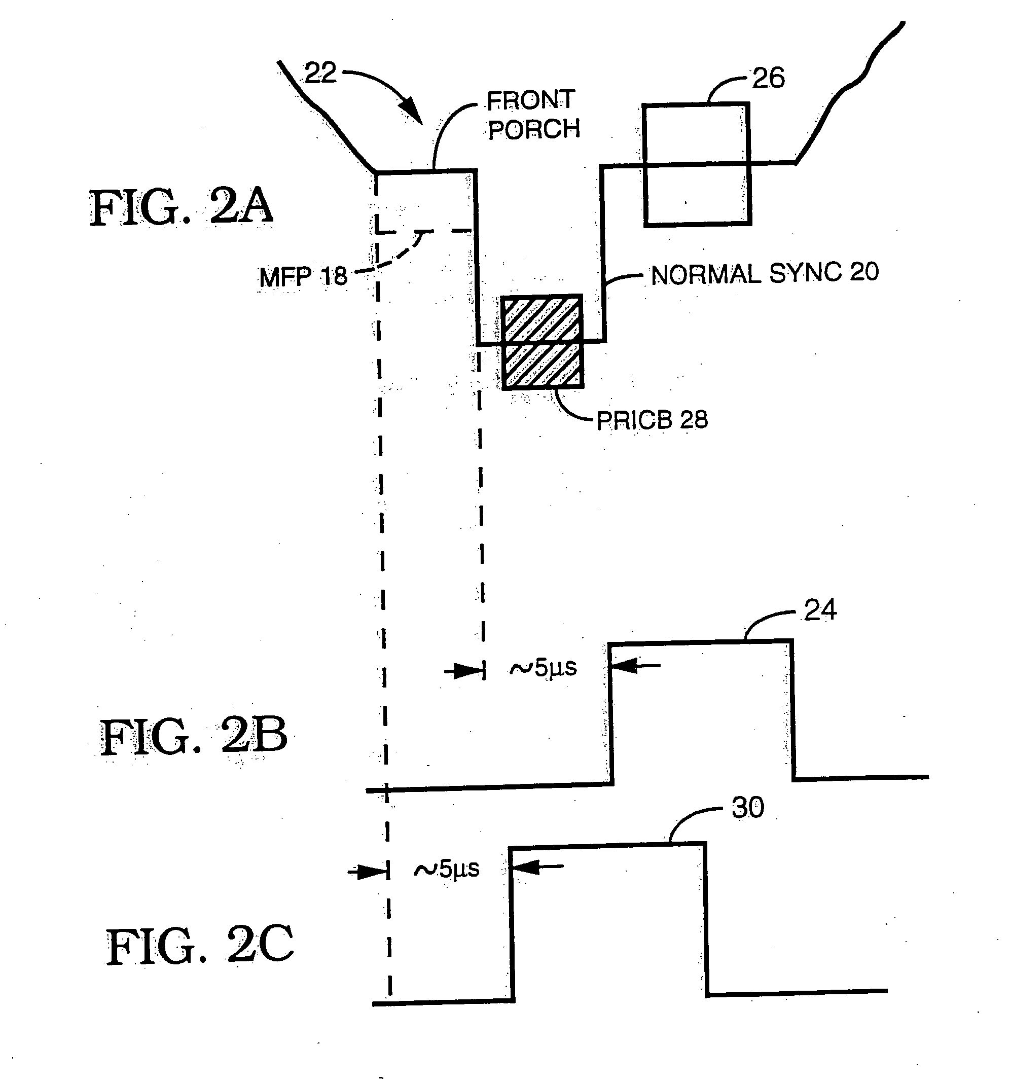
a signal level portion and signal technology, applied in the field of copy protection processes, can solve the problems of early horizontal flyback or burst pulse, and achieve the effects of increasing concealment, causing more color distortion, and maximizing the extra darkening

Inactive Publication Date: 2006-03-16
ROVI SOLUTIONS CORP
View PDF8 Cites 18 Cited by
  • Summary
  • Abstract
  • Description
  • Claims
  • Application Information

AI Technical Summary

Benefits of technology

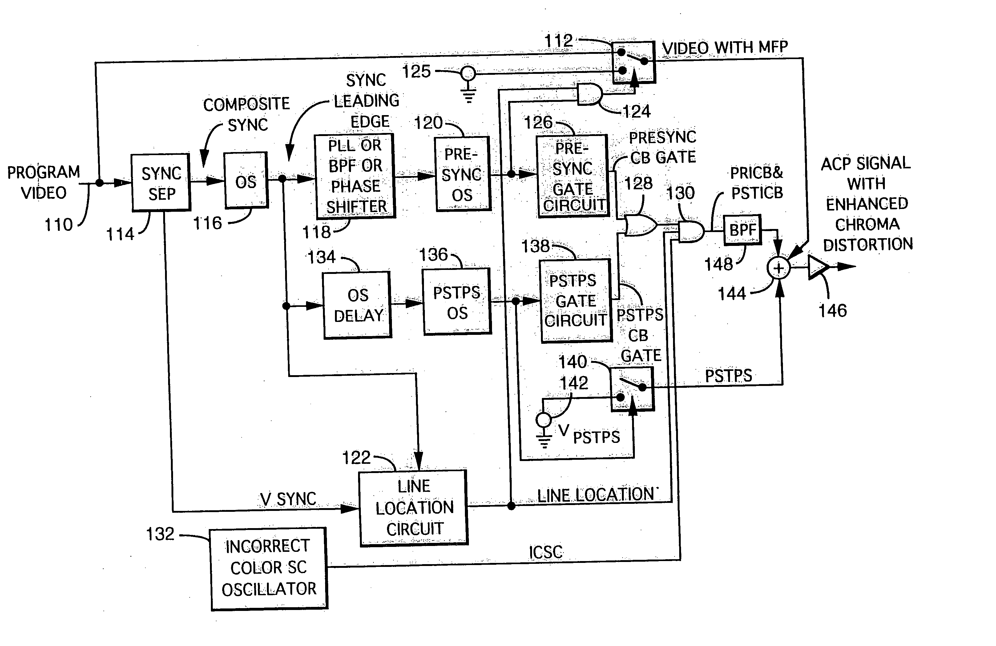
[0020] An advantage of the invention is that the incorrect color signals generally are not sensed by the circuits when the video signal is supplied directly to a normal TV set, whereby a normal picture is displayed, whereas the prior art color stripe video copy protection signals are sensed by the TV set. Of course, the present invention may be combined with various prior art video copy protection processes including the color stripe process of previous mention, or its variations such as that using segmented color bursts.
[0021] A modified color burst comprising an incorrect color subcarrier for example, may be a waveform having a frequency which various from the color subcarrier frequency. However, the waveform may be phase, frequency, and / or amplitude modulated. One function of the incorrect color burst is to cause improper static and / or dynamic color hues. Another function of the incorrect color burst signal is to cause static and / or dynamic color saturation.
[0022] An alternative modification of the color burst signal may be achieved by varying the phase from field to field as to cause for example, color flicker within a frequency range of 1 HZ to 25 HZ.
[0023] In a further embodiment, the post pseudo sync signal is moved toward the beginning of the TV line by sensing the active video portion, to thereby maximize the extra darkening. That is, the post pseudo sync (PSTPS) signal is inserted near the beginning of the video line whenever there is a voltage level in the beginning of active video which is greater than black level. The greater than black level then behaves as an AGC pulse with respect to the post pseudo sync signal. The movement of the post pseudo sync signal can be done dynamically by sensing the video levels of the first few microseconds of the active video lines. When a gray to white level is sensed, the PSTPS signal is moved toward the beginning of the video line, i.e., to the end of the horizontal blanking interval (HBI).
[0024] Another embodiment of the invention may employ parts of the previous embodiment within certain video scrambling systems such as sync suppression scrambling systems. For example, the placement of an incorrect color burst in the sync signal area of a sync suppression system can result in increased concealment. In the case of an improved sync suppression system where blanking to predetermined levels (i.e., blanking level) of areas just outside the horizontal blanking interval, (HBI) such as the last and beginning 2 μs of the video line, the insertion of incorrect color burst in the sync signal area (i.e., at least a portion of the sync tip area, and the sync tip area and at least a portion of the back porch area), will cause more color distortions, especially when the 2 μs area of the video signal before the HBI is blanked.
[0025] Also included in the description of the present invention are various methods and / or apparatuses for at least weakening the effects of the color burst modifying process of previous discussion.

Problems solved by technology

In this particular case, the TV set will scan prematurely due to the pre pseudo sync signal and the attenuated video signal, to thus cause an early horizontal flyback or burst pulse.

Method used


Image

  • Method and apparatus for synthesizing or modifying a copy protection signal using a lowered signal level portion
  • Method and apparatus for synthesizing or modifying a copy protection signal using a lowered signal level portion
  • Method and apparatus for synthesizing or modifying a copy protection signal using a lowered signal level portion

Examples


Embodiment Construction

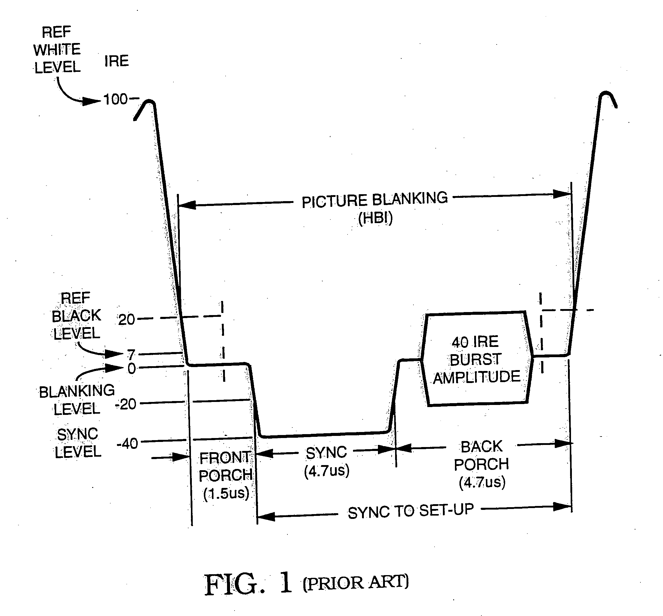
[0039]FIG. 1 depicts by way of example a normal or standard horizontal blanking interval (HBI) in a video line of a television signal. In particular, the FIG. 1 shows the end of one line of active video and the HBI, followed by the beginning of a subsequent line of active video. The HBI includes a front porch of for example 1.5 microseconds (μs), a horizontal sync signal of 4.7 μs and a back porch of about 4.7 μs, with the front and back porches set at blanking level (zero IRE) and sync tip set at −40 IRE. Reference black level is for example +7 IRE, and a color burst signal of 40 IRE amplitude is disposed on the back porch following the sync signal.

[0040] As previously discussed, the present invention preferably requires the attenuation affects imparted to a video signal by a typical anti-copy protection (ACP) process to initiate the incorrect triggering and / or sampling in a TV set and / or VCR, to thereby cause further enhancement of the chroma distortion of the copy protected vide...


PUM


Abstract

A modified Colorstripe™ copy protection process utilizes a basic anti-copy protection (ACP) signal that causes attenuation of a video signal, wherein, in one embodiment, the process modifies (lowers) the level of a front porch portion and adds an incorrect color signal (color burst) in the region of the sync tip. When an illegal copy is made, a pre-blanked end of line portion causes a TV set to trigger the color burst sample pulse ahead of time and cause the incorrect color signal in the sync tip region to be sampled. Thus, since the sync tip region has incorrect color phase or frequency, the resulting illegal copy will have enhanced color distortions. In other embodiments, other portions of the horizontal blanking interval are lowered in level and incorrect color bursts are added to a portion or portions of the back porch and / or a portion of the front porch. A further embodiment employs lowering a back porch portion above a sync tip level near the beginning of a video line to form a pseudo sync / AGC pulse pair. The various embodiments of the process may include an adaptable process, as well as several alternative ACP signals for use in combination with the process.

Description

BACKGROUND OF THE INVENTION [0001] The present invention is related to copy protection processes such as those which cause a darkening or lightening effect in an illegal copy of a video signal when displayed, and more particularly to a copy protection process which enhances the copy protection effect by adding further chroma distortion to an illegal copy of the copy protected video signal. [0002] It follows therefore that a preferred embodiment of the invention is used in combination with typical copy protection processes which selectively attenuate the video signal. Such video copy protection signals typically may consist of sync or pseudo sync and automatic gain control (AGC) pulses. In a video cassette recorder (VCR), erroneous gain levels are generated by the sync and / or pseudo sync / AGC signals, which cause the VCR to turn down the video gain. Once the video gain is turned down, a number of enhancement signals may be added primarily to affect the integrity of the sync signal in ...

Claims


Application Information

Patent Timeline
IPC IPC(8): H04N5/76G11B15/04G11B19/04H04N5/91G11B20/00H04N5/913H04N9/64H04N9/79H04N9/793
CPCG11B20/00086G11B20/0063G11B20/00826H04N2005/91371H04N9/64H04N2005/91314H04N5/913
Inventor QUAN, RONALD
Owner ROVI SOLUTIONS CORP
Learn More