Single-frequency network-based passive radar system and signal processing method for same

An external radiation source radar and signal processing technology, applied in the direction of radio wave reflection/re-radiation, utilization of re-radiation, radio wave measurement system, etc. To achieve the effect of simplified hardware equipment, good concealment, and flexible networking

Active Publication Date: 2014-04-02
武汉鉴观科技有限公司
View PDF3 Cites 32 Cited by
  • Summary
  • Abstract
  • Description
  • Claims
  • Application Information

AI Technical Summary

Problems solved by technology

However, while the SFN distributed external radiator radar enjoys many advantages, the introduction of the SFN also brings a series of new problems that have not been encountered in conventional external radiator radars or have not been encountered.
These core problems are mainly reflected in: 1) In the single frequency network, each station transmits the same continuous wave signal at the same frequency, and the direct wave, multipath clutter, and ground clutter of all stations are collected in the receiving channel, which is better than the clutter of a single station. It is more serious and affects the target detection; 2) Similarly, the scattered echoes of the target generated by each station irradiating the target are received, and multiple measurements are formed after the correlation detection, and the corresponding relationship between each measurement and the transmitting station is unknown a priori. This leads to ambiguity in target positioning, which is called the SFN ambiguity problem

Method used


Image

  • Single-frequency network-based passive radar system and signal processing method for same
  • Single-frequency network-based passive radar system and signal processing method for same
  • Single-frequency network-based passive radar system and signal processing method for same

Examples


Embodiment Construction

[0038] The present invention will be further described below with specific embodiments in conjunction with the accompanying drawings.

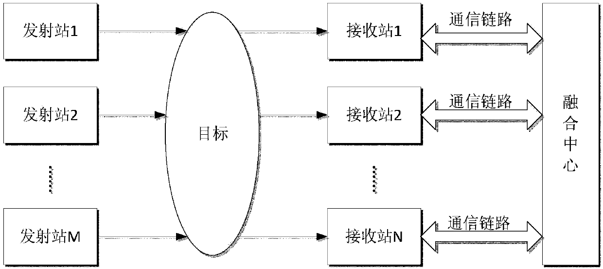
[0039] see figure 1, the present invention includes M transmitting stations (forming a single frequency network), N receiving stations, a fusion center, and communication links. M transmitting stations form a single-frequency network, and transmit the same signal at the same frequency at the same time; N receiving stations are arranged in a distributed manner to receive signals independently, and a single receiving station and M transmitting stations can independently form a MISO system; when N is greater than 1, another A fusion center, where communication and data transmission are performed between the fusion center and each receiving station through a communication link. When the system is working, M transmitting stations radiate electromagnetic signals to act on the target of interest, and the target forms a scattering of electromagnetic ...


PUM


Abstract

The invention provides a single-frequency network-based passive radar system and a signal processing method for the same. A plurality of illumination sources for the system are used for simultaneously transmitting the same signals at the same frequency, and namely work in a single-frequency network system. A plurality of transmission stations and one or more receiving stations form a MISO (multiple-input single-output) or MIMO (multiple-input multiple-output) detection system, wherein the MIMO system is provided with a fusion center for performing communication and data transmission with each receiving station through a communication link and fusing processing results of each receiving station, and works at the same frequency; each transmission station is in the same form, and each receiving station is in the same form. A one-stop space-domain processing and single-frequency network defuzzification method is adopted for the signal processing method. According to the system and the method, a conventional broadcasting single-frequency network is used under the condition of no interference on broadcasting, so that the problems of severe clutter caused by the single-frequency network and fuzziness of the single-frequency network are solved, and the advantages of single-frequency network detection in frequency power reduction, hardware saving, detection stability and tracking continuity are fully exerted.

Description

technical field [0001] The present invention relates to the technical field of external radiation source radar, in particular to a system and method for detecting a target by using a single-frequency network digital broadcasting and television illumination source, specifically a single-frequency network-based external radiation source radar system and a signal processing method thereof. Background technique [0002] External radiation source radar (also known as passive radar) is an ancient and emerging radar system. Its core feature is that it does not need to provide its own emission source, but uses electromagnetic signals emitted by a third party to detect targets, so it has low cost and concealment. Good performance, strong anti-interference ability, good electromagnetic compatibility and many other advantages. As early as 1935, the Davertry experiment conducted by Arnod Wilkins in the United Kingdom detected bombers flying nearby by using third-party radiation signals ...

Claims


Application Information

Patent Timeline
Patent Type & Authority Applications(China)
IPC IPC(8): G01S13/66
CPCG01S13/66
Inventor 万显荣易建新柯亨玉程丰饶云华龚子平
Owner 武汉鉴观科技有限公司
Why Eureka
Try Eureka