Low-profile screen framing system

a low-profile, frame-type technology, applied in the direction of door/window protective devices, building components, constructions, etc., can solve the problems of unfinished appearance, increased cost and installation time, and ongoing maintenance, so as to achieve easy replacement, maintain an aesthetically pleasing structure, and easy to snap

Active Publication Date: 2011-01-04
MARHAYDUE
View PDF27 Cites 18 Cited by
  • Summary
  • Abstract
  • Description
  • Claims
  • Application Information

AI Technical Summary

Benefits of technology

Yet another feature of the present invention includes the use of a frame element that can be concealed within a framework through the use of routed support elements. In particular, support members can include cut-outs having dimensions that are about the same as those of the frame element, so that the frame element is received by and concealed within the support members. The result is a flush and much more finished appearance for the framework of a screen-in porch and yet one that still allows the screens to be easily replaced as needed. Accordingly, this feature provides flexibility in construction choices, while still maintaining an aesthetically pleasing structure.
Another feature of the present invention includes the use of a button that is dimensioned to be received by the slot of the frame element so that the frame element can be attached to a variety of frameworks. The buttons can be made of plastic, such as nylon, either with a hole for a conventional metal screw or with an integral screw of plastic. The head of the button is shaped to allow the frame element to be easily snapped over it; that is, the button is just slightly larger than the width of the slot. Alternatively, the button can be a clip that is one-piece, having a head portion and a post portion.

Problems solved by technology

Both the fasteners employed to erect the porch and the post and beam construction contributes to an unfinished appearance.
This framing may require the use of furring strips to cover attaching means, which further increases the cost and installation time.
Moreover, the installation of the screen, as well as ongoing maintenance, must be done at elevated, potential dangerous heights.
Ladders must be employed, which contributes to the unstable and inconvenient aspects of installing and maintaining multi-level porches.
Some are difficult to install, are obtrusive or lack a finished appearance.
Additionally, special mounting procedures to attach screens to frames may need to be employed, which further complicates the process of erecting screen porches.

Method used


Image

  • Low-profile screen framing system
  • Low-profile screen framing system
  • Low-profile screen framing system

Examples


Embodiment Construction

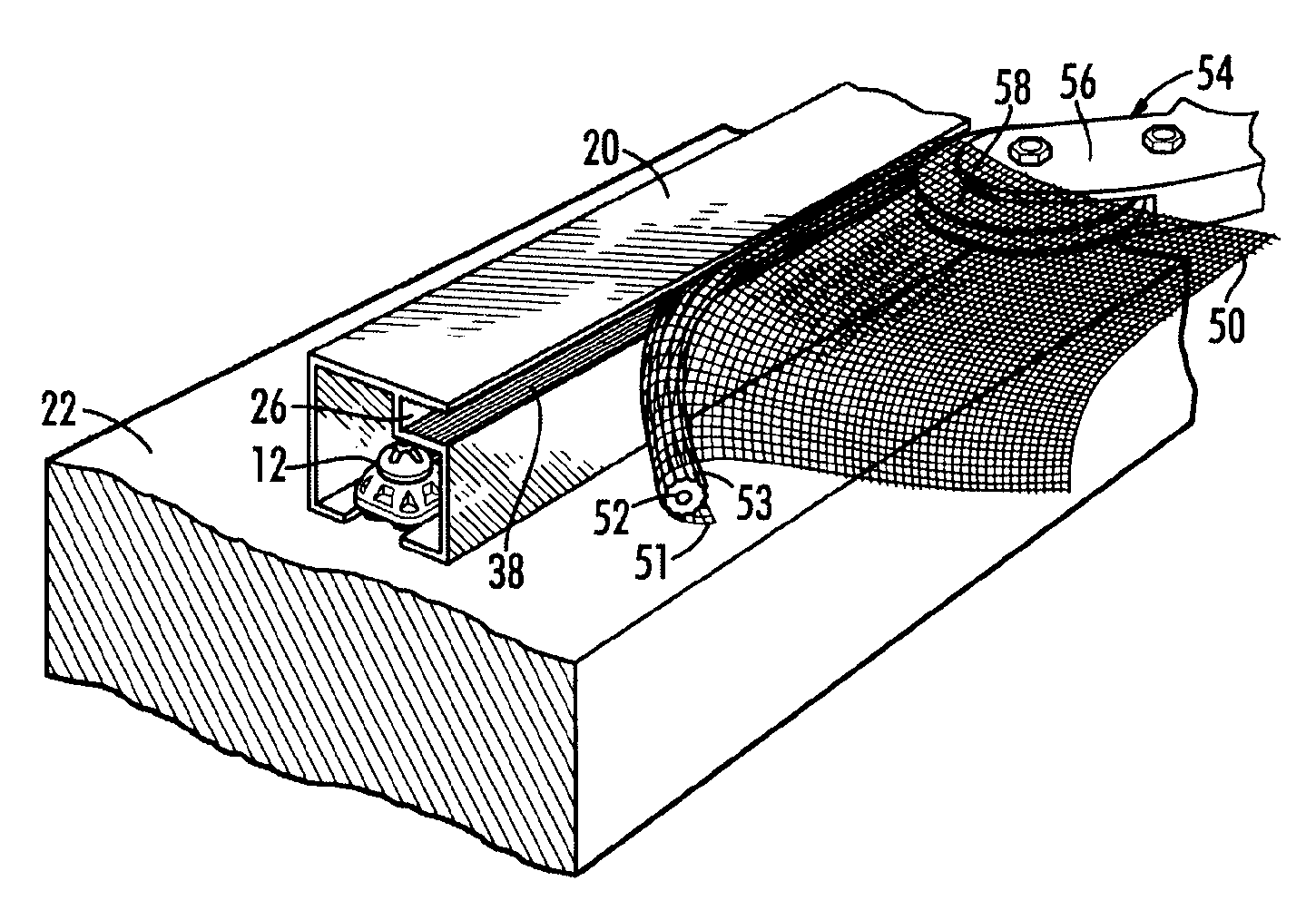
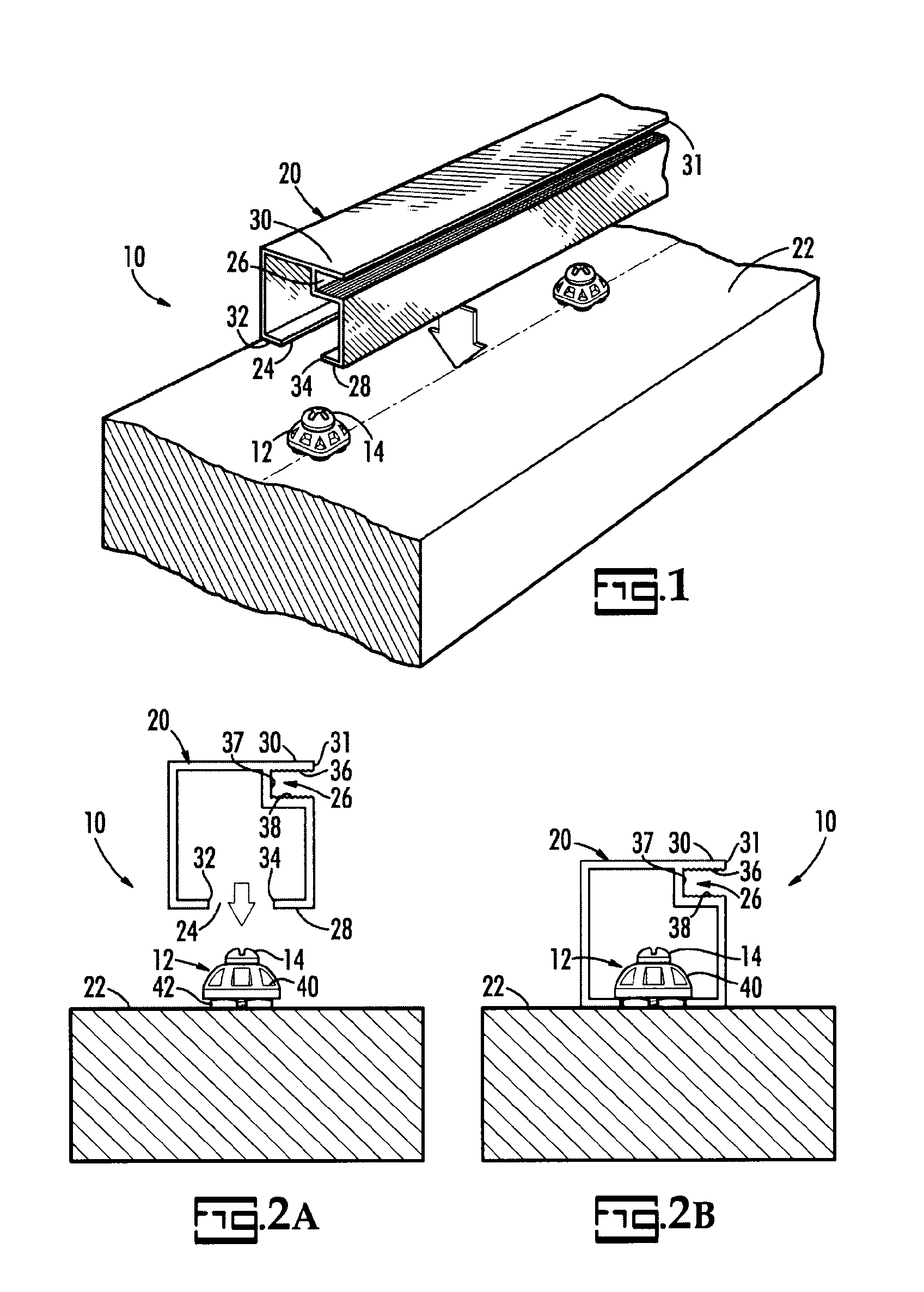
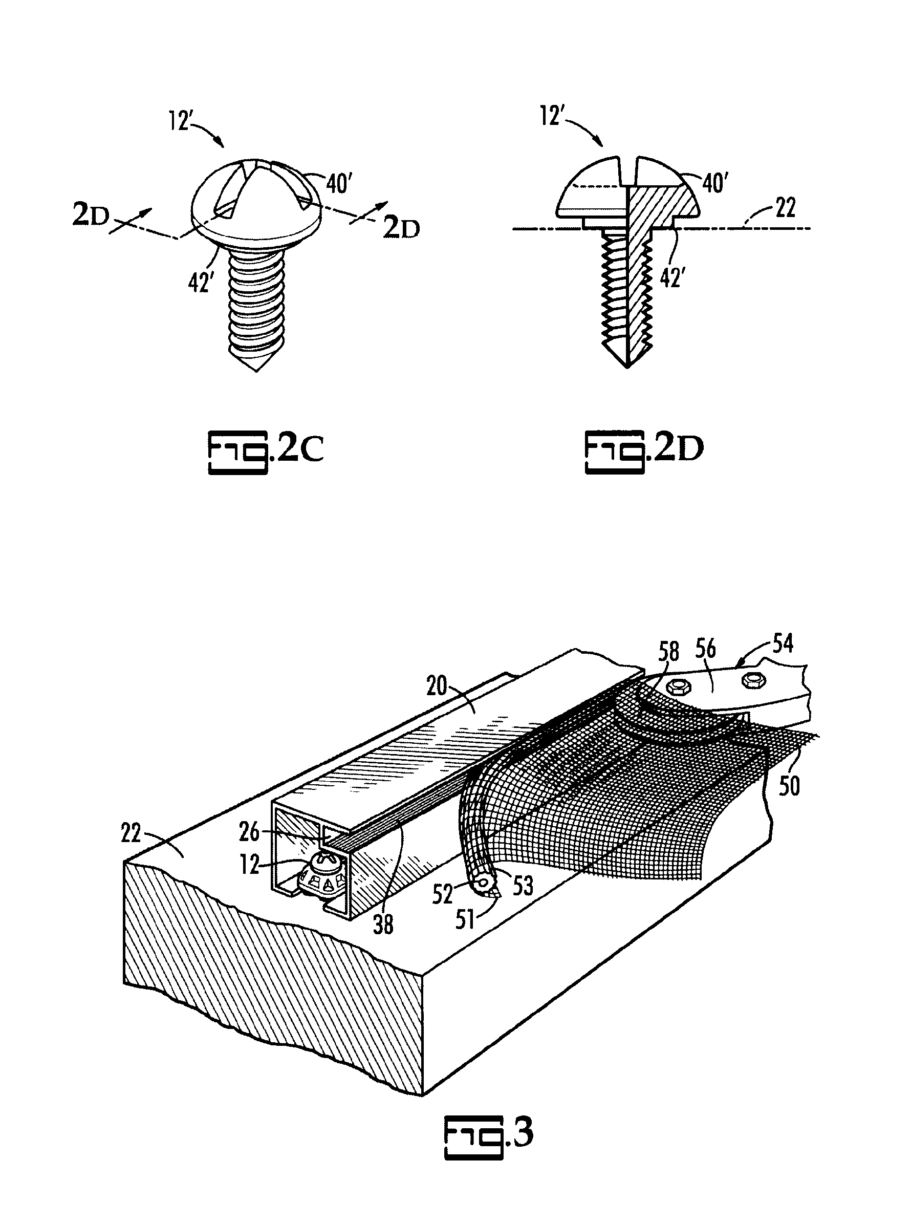
The present invention is a system for attaching screening to a framework. As illustrated in FIG. 1, the framing system 10 includes a button 12 with a separate or integral means for attaching, such as a screw 14, and a frame element 20 that are combined with a support member, such as a post 22, of a framework. The frame element 20 preferably has a square cross section in the shape of a squared letter C with the opening of the C defining a slot 24 cut into one side 28 of frame element 20 that extends longitudinally along the length of frame element 20. In a corner 31 of the opposing side 30 of frame element 20 is a longitudinally extending spline groove 26. The spline groove 26 preferably has a U-shaped cross section and is defined by an upper wall 36 and lower wall 38 spaced apart and connected by a side wall 37. Preferably, the surfaces of upper and lower walls 36, 38 are ridged to better retain splines and screens by frictional engagement when these features are applied.

Preferably,...


PUM


Abstract

A system for framing a porch using concealed fasteners and concealed or partially-concealed framing elements on support posts. The framing elements have a small cross section, generally shaped like the letter C with a slot on one side and a spline groove in one of the opposing corners. The framing elements are attached to a support post by screwing plural, spaced-apart buttons into the posts and then snapping the button heads into the slot of the framing elements. The framing elements may be applied to the surface of the posts or, because of their small size, may be put into grooves formed in the sides or corners of the posts and concealed on one or more sides by trim boards.

Description

BACKGROUND OF THE INVENTIONThe present invention relates to framing systems for fixed screens and, more particularly, to low-profile frame members for fastening screens to framing such as are used for porches.Screened porches remain a popular addition to constructions, as they enhance the enjoyment of the out-of-doors regardless of ambient conditions. The screening blocks the entry of insects and admits air to the area of the porch so enclosed. Typically, porches are screened by erecting a simple wooden framing to enclose the porch in a series of panels and to which the screening material is nailed or tacked. Additionally, screened enclosures often utilize beams and posts or columns in their construction. Both the fasteners employed to erect the porch and the post and beam construction contributes to an unfinished appearance. It is thus desirable to conceal these features to enhance the appearance and enjoyment of the screen porches.In some areas of the country, such as along the se...

Claims


Application Information

Patent Timeline
Patent Type & Authority Patents(United States)
IPC IPC(8): E06B1/18E06B9/00E06B1/32
CPCE06B9/52E06B9/521
Inventor GREEN, GUERRY E.
Owner MARHAYDUE
Why Eureka
Try Eureka