
Rotatable assemblies and methods of securing such assemblies

a technology of rotating assemblies and assemblies, applied in the direction of current collectors, non-rotary current collectors, electrical devices, etc., can solve the problems of twisted or otherwise deformed cables, disconnecting,

Inactive Publication Date: 2006-06-20
SMAR RES CORP
View PDF19 Cites 40 Cited by
  • Summary
  • Abstract
  • Description
  • Claims
  • Application Information

AI Technical Summary

Benefits of technology

[0005]One of the advantages of the present invention is that a first field device housing arrangement which is associated with a first electrical system is connected via a connector arrangement to a second field device housing arrangement which is associated with a second electrical system. Moreover, the connector arrangement is configured to allow an unrestricted rotation of the first field device housing arrangement relative to the second field device housing arrangement while maintaining a continuous electrical coupling between the first electrical system and the second electrical system. Further, there may be no need to facilitate internal cables or wires to be provided between the first field device housing arrangement and the second field device housing arrangement. In operation, when the first field device housing arrangement is rotated relative to the second field device housing arrangement, the electrical coupling between the first electrical system and the second electrical system is preferably prevented from being disrupted.
[0008]In yet another embodiment of the present invention, the cap element may include a hole formed therethrough, and a cross-sectional area of the hole can be less than a cross-sectional area of the head portion of the at least one securing element. Thus, a tool element (e.g., an Allen Hex Tool) can be inserted through the hole in order to loosen the at least one securing element, with the cap element preventing the securing element from being removed from the passage. When the securing element is loosened, the first field device housing arrangement can be unrestrictedly rotated relative to the second field device housing arrangement. For example, a tip of the securing element may be at least partially disengaged from the second field device housing arrangement or the third field device housing arrangement without being entirely removed from the recess. Such positioning of the tip of the securing element can prevent the second field device housing arrangement from being entirely detached from the first field device housing arrangement when the first field device housing arrangement is rotated with respect to the second field device housing arrangement.

Problems solved by technology

Nevertheless, if the electronics housing is rotated by more than 720°, the cable may become twisted or otherwise deformed, as well as become disconnected from the circuit board that is positioned inside the sensor housing.

Method used


Image

  • Rotatable assemblies and methods of securing such assemblies
  • Rotatable assemblies and methods of securing such assemblies
  • Rotatable assemblies and methods of securing such assemblies

Examples


Embodiment Construction

[0019]Exemplary embodiments of the present invention and their advantages may be understood by referring to FIGS. 1a–6, like numerals being used for like corresponding parts in the various drawings.

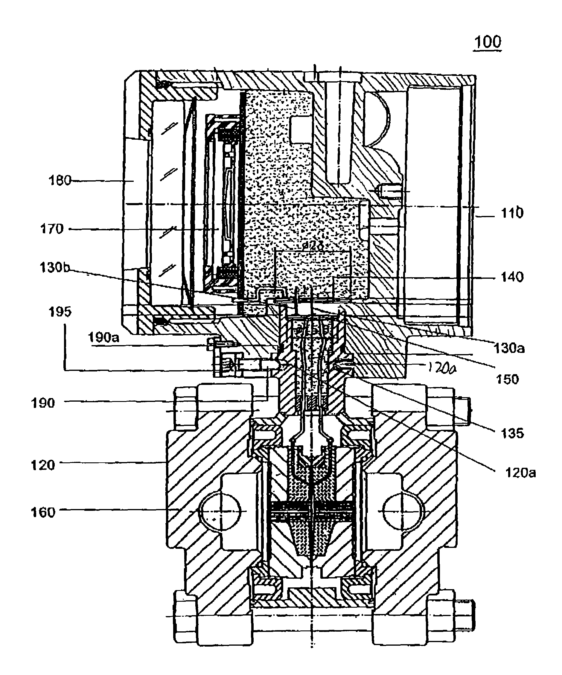
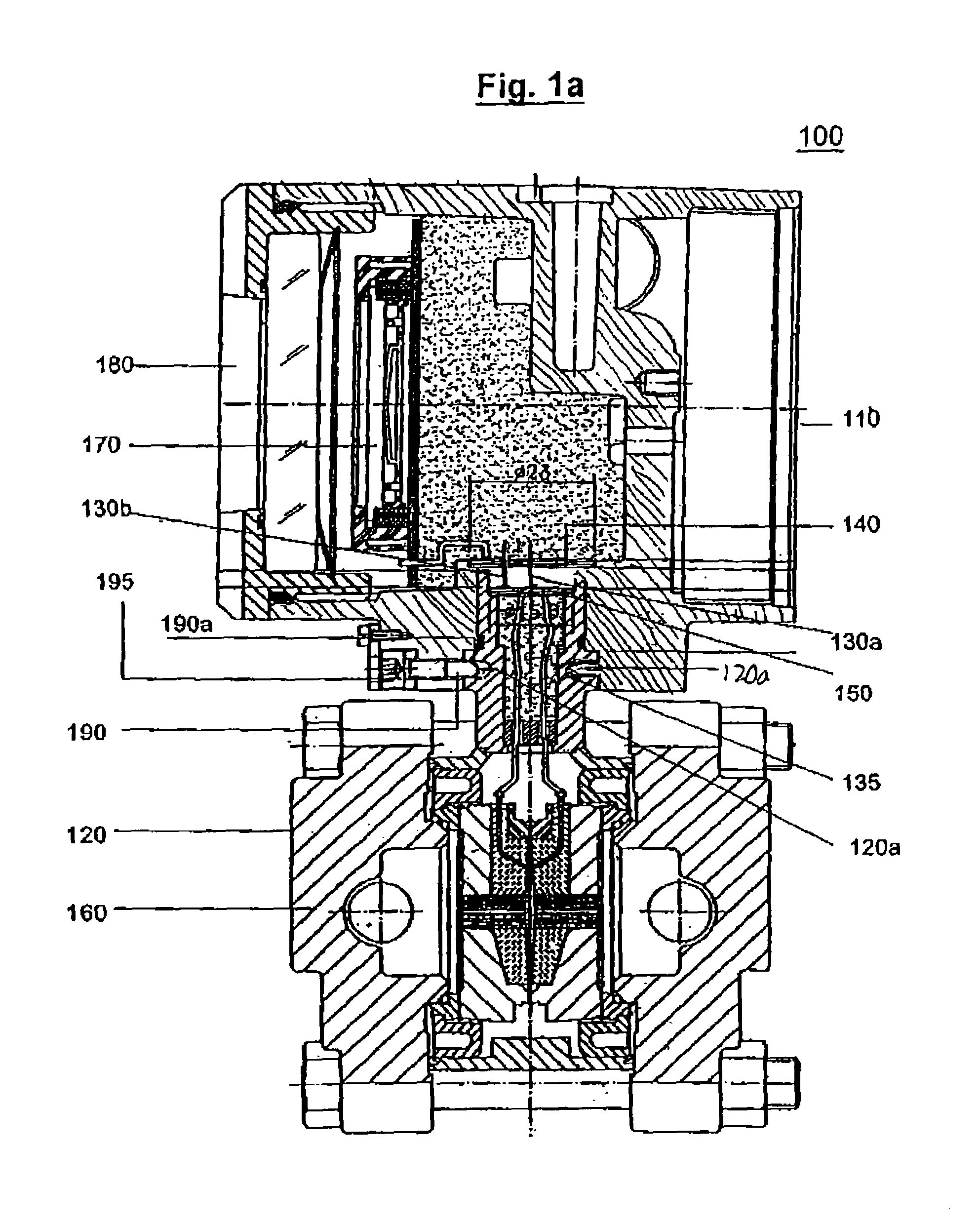
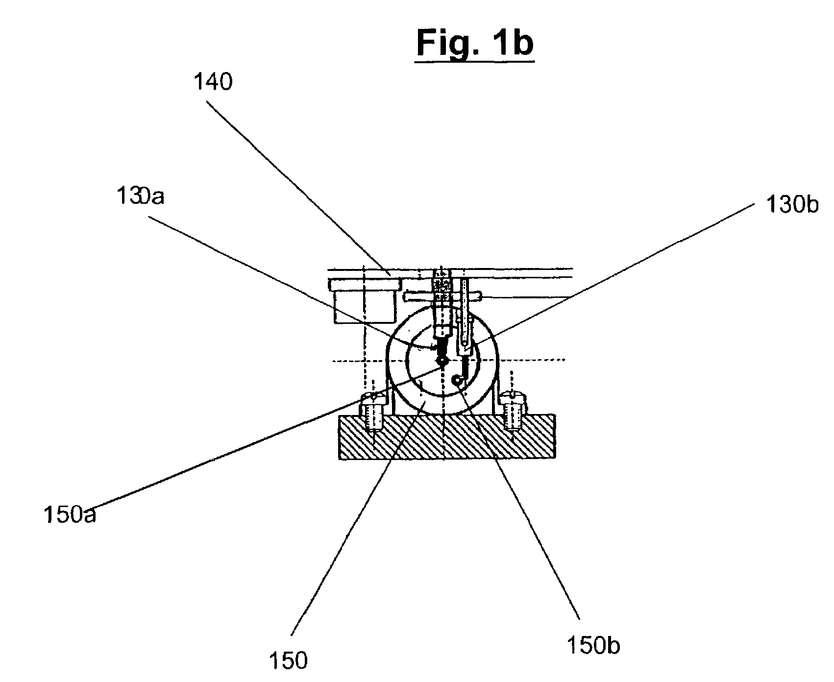
[0020]Referring to FIGS. 1a–4, a first exemplary embodiment of an assembly 100 (e.g., a field device, such as a smart field device) according to the present invention is provided. The assembly 100 may include a first field device housing arrangement 110 (e.g., an electronics housing arrangement) associated with a first electrical system, and a second field device housing arrangement 120 (e.g., a sensor housing arrangement) associated with a second electrical system. The first electrical system can include a display unit 170 and / or a first circuit fixture 140 (e.g., a metal plate) positioned inside the first field device housing arrangement 110. Moreover, the display unit 170 may include a display screen 180 which can be viewed by a user when the assembly 100 is in use. The display unit 17...


PUM


Abstract

A rotatable assembly and a method to use the same are provided. In particular, the assembly includes a first field device housing arrangement associated with a first electrical system, and a second field device housing arrangement associated with a second electrical system are connected by a connector arrangement. The connector arrangement may include probes (e.g., spring probes) that are adapted to engage with contacts (e.g., electrical contacts), and is configured to allow an unrestricted rotation of the first field device housing arrangement relative to the second field device housing arrangement while maintaining a continuous electrical coupling between the first electrical system and the second electrical system. For example, the assembly can be a field device, such as a smart field device. Two devices may be secured to one another by use of a captive locking screw which can be used to secure the first device in desired positions.

Description

FIELD OF THE INVENTION[0001]The present invention relates generally to assembly and method in which a first field device housing arrangement associated with a first electrical system is rotatable with respect to a second field device housing arrangement associated with a second electrical system using a connector arrangement. In particular, the present invention is directed to the assembly and method in which the connector arrangement is configured to allow an unrestricted rotation of the first field device housing arrangement relative to the second field device housing arrangement while maintaining a continuous electrical coupling between the first electrical system and the second electrical system.BACKGROUND OF THE INVENTION[0002]Conventional field devices, such as conventional smart field devices, may include a sensor housing and an electronics housing which are interconnected during their assembly. For example, the electronics housing may be connected to the sensor housing using...

Claims


Application Information

Patent Timeline
Patent Type & Authority Patents(United States)
IPC IPC(8): H01R39/00H01R35/00
CPCH01R35/00Y10S248/922
Inventor SELLI, BASILIOGULLO, GERALDO
Owner SMAR RES CORP
Learn More