Fracture fixation device having clip for stabilizing intramedullary nail

a fixation device and intramedullary nail technology, applied in the direction of osteosynthesis devices, internal osteosythesis, bone plates, etc., can solve the problems of difficult to create a tight fit between the nails and the medullary canal at the fracture site, and the use of flexible intramedullary nails is challenging

Active Publication Date: 2017-02-16
THE GENERAL HOSPITAL CORP
View PDF31 Cites 39 Cited by
  • Summary
  • Abstract
  • Description
  • Claims
  • Application Information

AI Technical Summary

Benefits of technology

[0007]The present disclosure meets the foregoing needs by providing a fracture fixation device including a nail section and a nail fastening section. The nail section is dimensioned to be positioned within an intramedullary canal of a bone such that the nail section spans a fracture site in the bone. Preferably, the nail section has a pre-insertion configuration, and the nail section comprises a flexible material such that when the nail section is inserted in the intramedullary canal, the nail section bends into a post-insertion configuration different from the pre-insertion configuration. When bending into the post-insertion configuration, the nail section creates frictional force at points where the nail section contacts an inner surface of the intramedullary canal. The nail fastening section is connected to the nail section by a connecting element on a first side of the fracture site. At least a portion of the nail fastening section is positioned outside the bone when the fracture fixation device is implanted in the bone. A first end of the nail section and a second end of the nail fastening section are positioned on an opposite second side of the fracture site when the fracture fixation device is implanted in the bone of a subject. When the bone of the subject has a growth plate (as in a pediatric bone), flexibility of the nail section allows the nail section to be inserted at a point in the bone that avoids disruption of the growth plate.

Problems solved by technology

However, there are long bone fractures for which the use of flexible intramedullary nails is challenging.
For example, when the fracture is at the proximal metaphysis where the medullary canal is wider (see FIG. 2B), creating a tight fit between the nails and the medullary canal at the fracture site is difficult.

Method used


Image

  • Fracture fixation device having clip for stabilizing intramedullary nail
  • Fracture fixation device having clip for stabilizing intramedullary nail
  • Fracture fixation device having clip for stabilizing intramedullary nail

Examples


Embodiment Construction

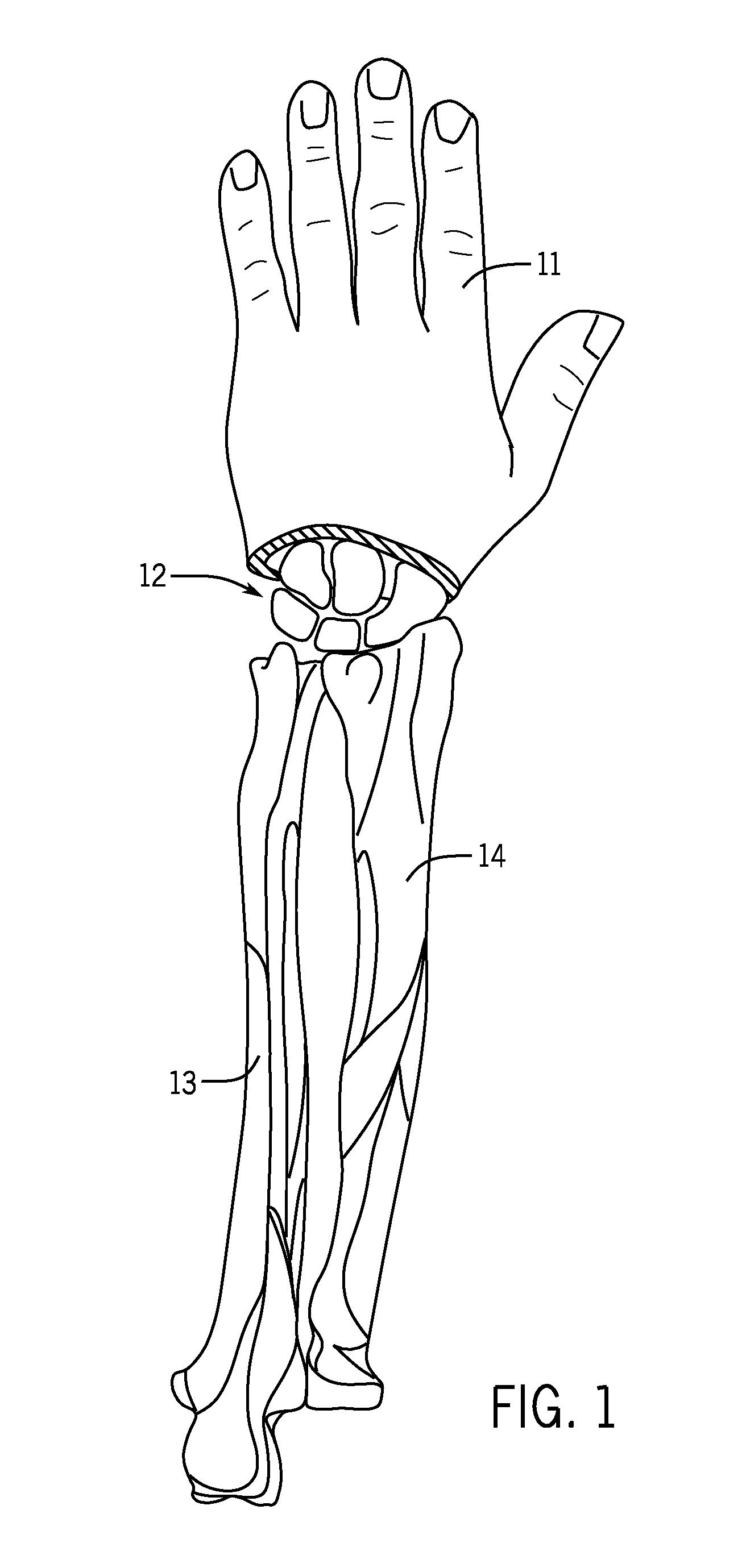
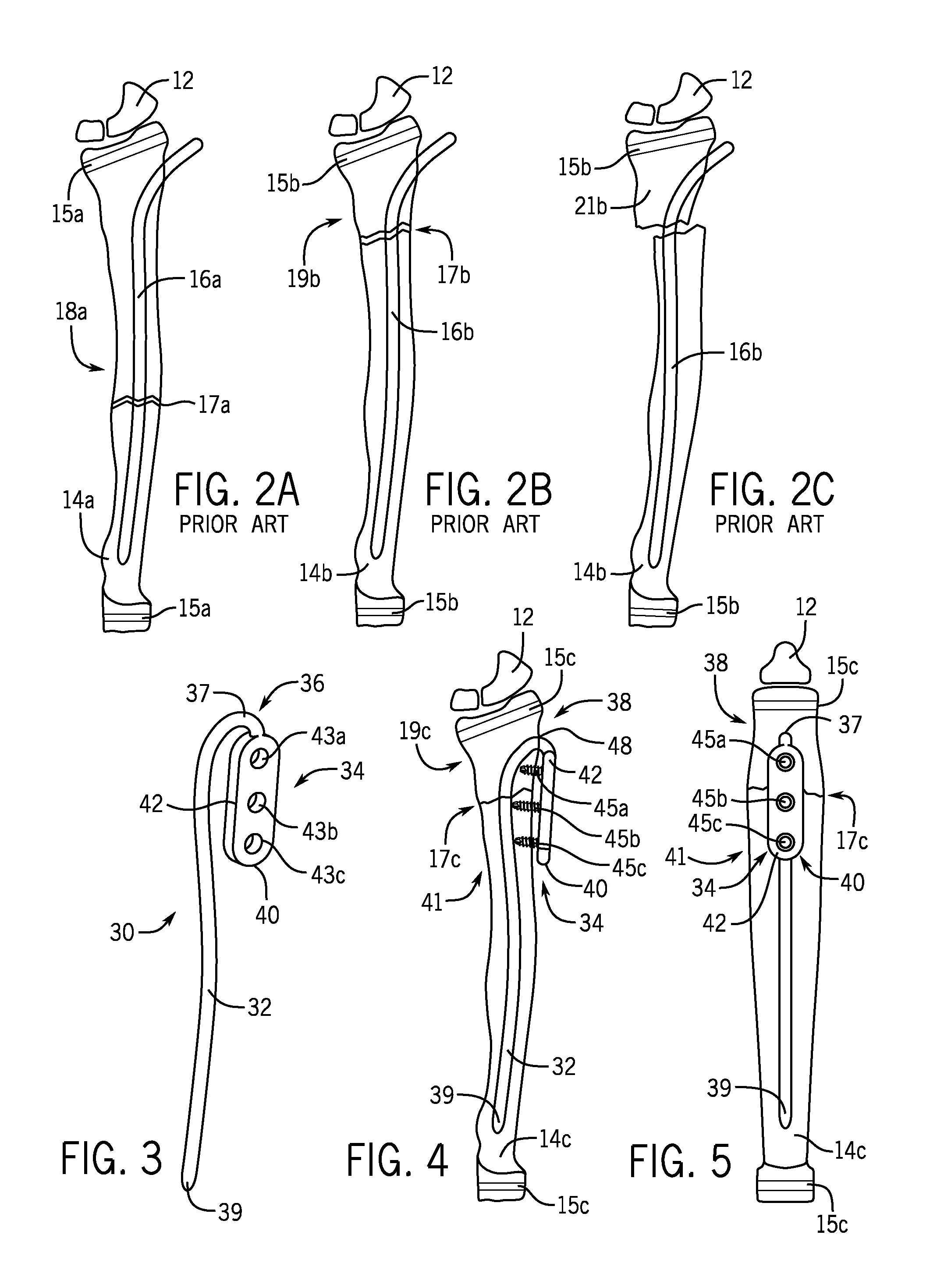
[0048]FIGS. 1 to 2C show prior methods for treating fractures in the distal human radius. FIG. 1 shows a human hand 11, carpal bones 12, the ulna 13, and the radius 14. FIG. 2A shows a pediatric radius 14a with growth plates 15a wherein a flexible intramedullary nail 16a has been used to treat a fracture 17a at the diaphysis 18a. FIG. 2B shows a pediatric radius 14b with growth plates 15b wherein a flexible intramedullary nail 16b has been used to treat a fracture 17b at the metaphysis 19b. FIG. 2C is a view of the treated radius 14b of FIG. 2B wherein displacement has occurred at the fracture site. Without a tight fit between the intramedullary canal and the intramedullary nail 16b, there is no control over the proximal fragment 21b, allowing the proximal fragment 21b to displace left in the view of FIG. 2C.

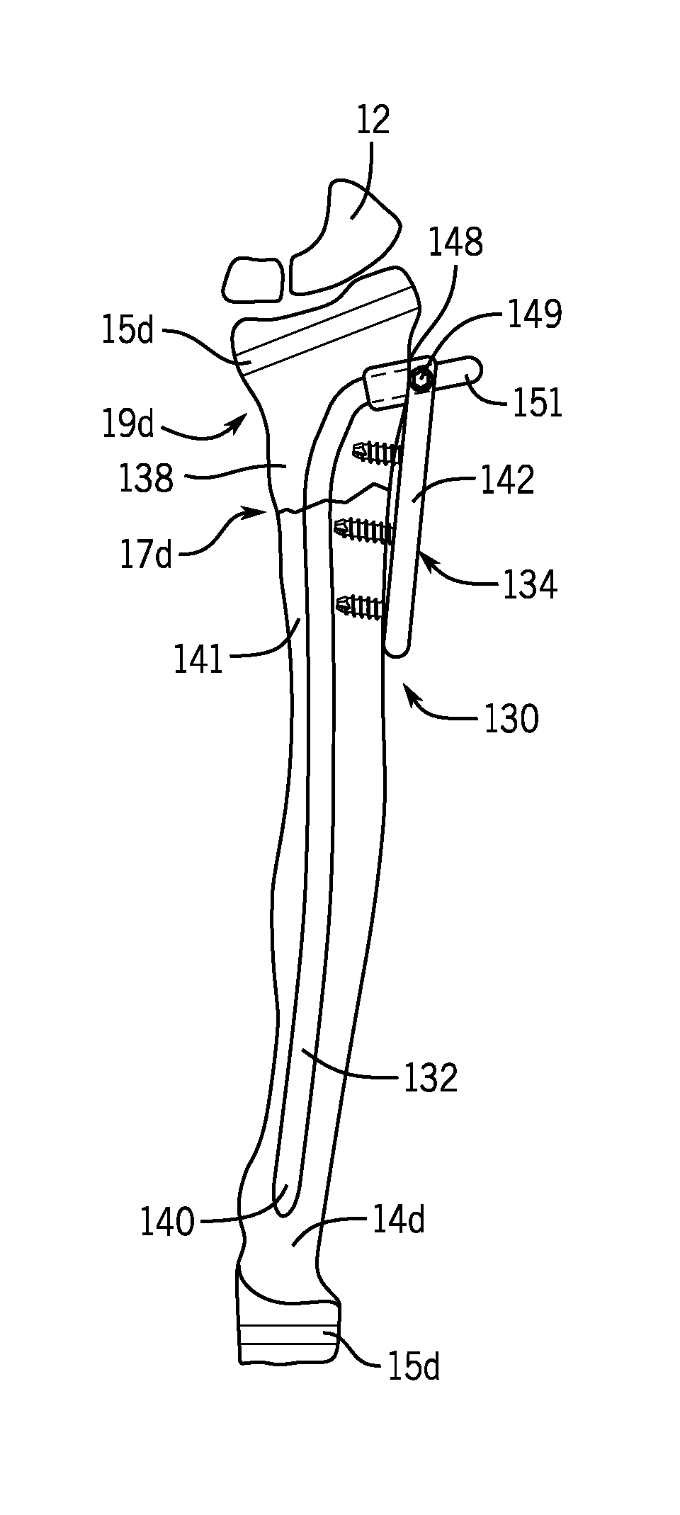
[0049]Turning now to FIGS. 3-5, there is shown an example embodiment of a fracture fixation device 30 of the present invention. The fracture fixation device 30 includes a nail s...


PUM


Abstract

Fracture fixation devices and methods achieve stabilization of a bone fragment. A nail section of the device is dimensioned to be positioned within an intramedullary canal of a bone such that the nail section spans a fracture site in the bone. The nail section bends into a post-insertion configuration different from a pre-insertion configuration when inserted into the intramedullary canal. The nail fastening section is connected to the nail section by a connecting element on a first side of the fracture site. At least a portion of the nail fastening section is positioned outside the bone. A first end of the nail section and a second end of the nail fastening section are positioned on an opposite second side of the fracture site when the fracture fixation device is implanted in the bone.

Description

CROSS-REFERENCE TO RELATED APPLICATIONS[0001]This application claims priority to U.S. Patent Application No. 61 / 981,946 filed Apr. 21, 2014.STATEMENT REGARDING FEDERALLY SPONSORED RESEARCH[0002]Not Applicable.FIELD OF THE INVENTION[0003]This invention relates to fracture fixation devices and methods.BACKGROUND OF THE INVENTION[0004]Flexible intramedullary nails are used to stabilize long bone fractures in pediatric patients. They are mostly used in forearm fractures (radius and ulna) as well as humerus, femur, and tibia fractures when casting is not appropriate. The nails work well when the fracture is at the diaphysis (the middle of the bone where the medullary canal is the narrowest—see FIG. 2A) because the tight fit between the nail and the medullary canal promote stability between the two, resulting in stability of the fracture at the diaphysis. Because the nails are inserted through a small incision, they allow minimally invasive surgical treatment of fractures.[0005]However, t...

Claims


Application Information

Patent Timeline
Patent Type & Authority Applications(United States)
IPC IPC(8): A61B17/72A61B17/74
CPCA61B17/7233A61B17/746A61B17/744A61B17/8061
Inventor KIM, SAECHIN
Owner THE GENERAL HOSPITAL CORP
Why Eureka
Try Eureka