
Method of forming a conformal spacer adjacent to a gate electrode structure

a technology of conformal spacer and gate electrode, which is applied in the direction of basic electric elements, electrical apparatus, and semiconductor devices, can solve the problems of reducing the flexibility of affecting the process complexity, and affecting the design of the lateral

Active Publication Date: 2006-06-20
ADVANCED MICRO DEVICES INC
View PDF5 Cites 41 Cited by
  • Summary
  • Abstract
  • Description
  • Claims
  • Application Information

AI Technical Summary

Benefits of technology

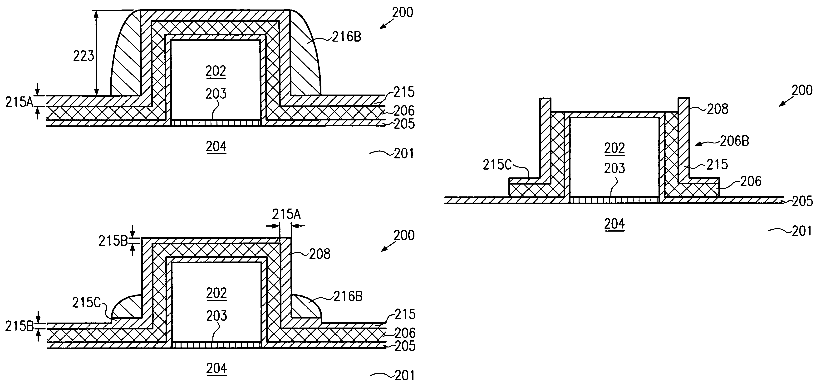
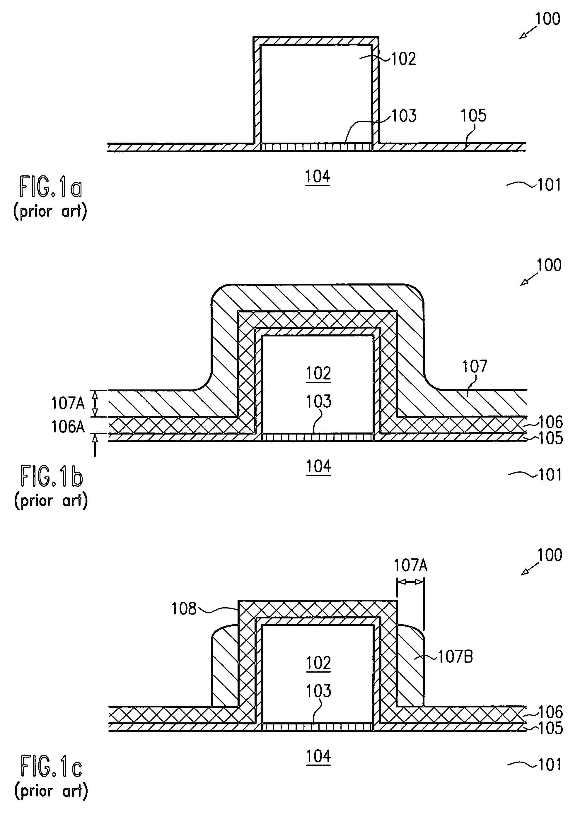
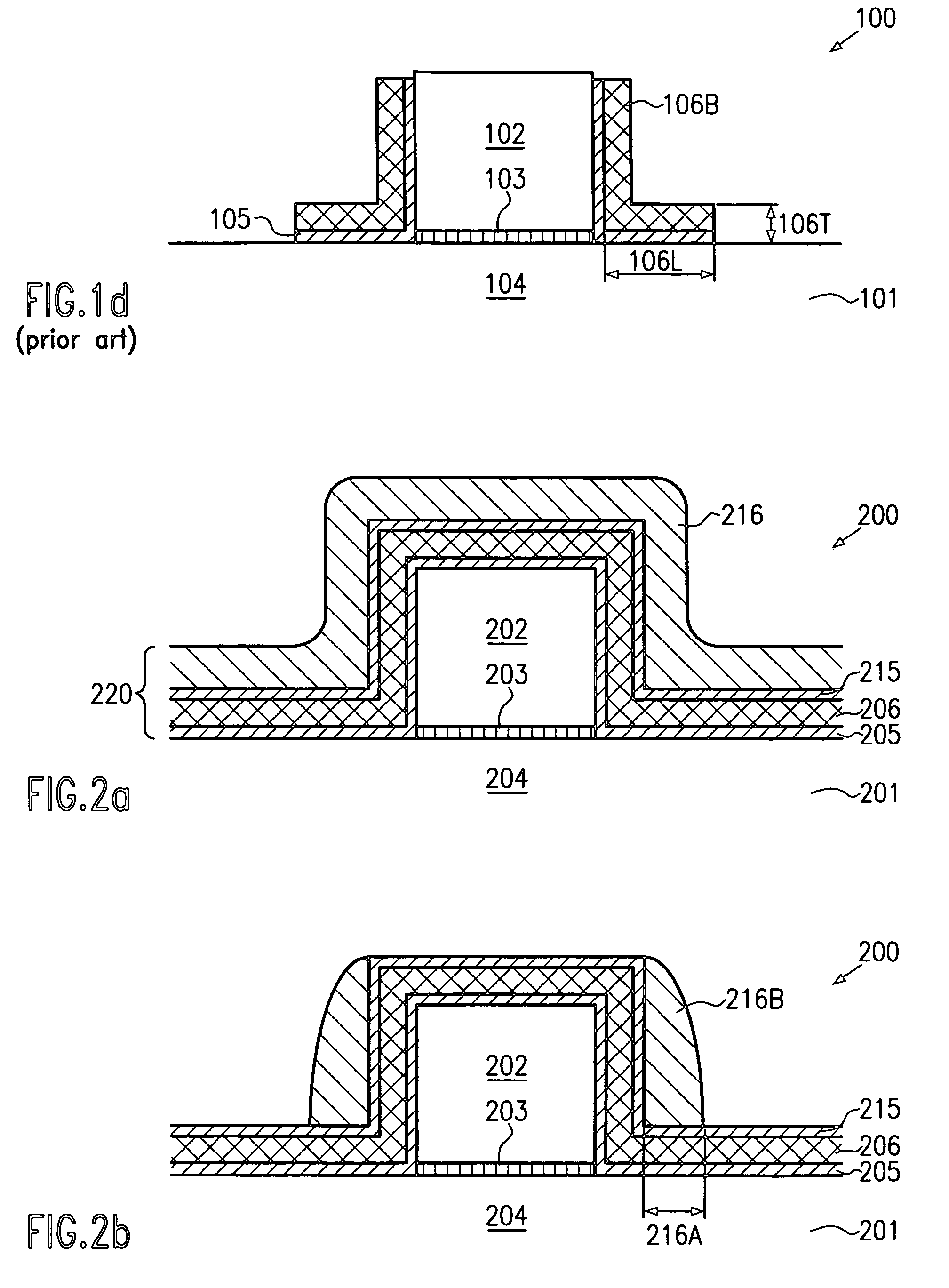
The present invention is about a technique for making conformal sidewall spacers during the fabrication of conductive lines, such as gate electrode structures of field effect transistors. The removal of sacrificial spacers can be done using the same etch chemistry as the conformal spacers. The sacrificial spacers and conformal spacers are made of silicon nitride with an etch stop layer in between. The method involves forming a conductive line, then sequentially adding layers of a material that can be selectively etched using the etch stop layer. The second layer is anisotropically etched to form sacrificial sidewall spacers, which are then removed. The conformal spacers are then formed by removing the sacrificial sidewall spacers and exposed portions of the first layer. This technique allows for the formation of conformal sidewall spacers without the need for a separate process.

Problems solved by technology

Although the above-described sidewall spacer technique is very efficient in the fabrication of CMOS devices having a gate length well beyond 0.2 μm, it turns out that for smaller feature sizes the formation of relatively bulky sidewall spacers may be disadvantageous in view of thermal stress exerted to the gate electrode and caused by the formation of the sidewall spacers.
Additionally, bulky sidewall spacers may not provide the required flexibility in designing the lateral dopant profile of the drain and source regions and the corresponding extension regions connecting to the channel region.
Consequently, additional reactive gases or other precursors required for the appropriate etch chemistry have to be provided in combination with a suitable etch tool, thereby contributing to process complexity.

Method used


Image

  • Method of forming a conformal spacer adjacent to a gate electrode structure
  • Method of forming a conformal spacer adjacent to a gate electrode structure
  • Method of forming a conformal spacer adjacent to a gate electrode structure

Examples


Embodiment Construction

[0024]Illustrative embodiments of the invention are described below. In the interest of clarity, not all features of an actual implementation are described in this specification. It will of course be appreciated that in the development of any such actual embodiment, numerous implementation-specific decisions must be made to achieve the developers' specific goals, such as compliance with system-related and business-related constraints, which will vary from one implementation to another. Moreover, it will be appreciated that such a development effort might be complex and time-consuming, but would nevertheless be a routine undertaking for those of ordinary skill in the art having the benefit of this disclosure.

[0025]The present invention will now be described with reference to the attached figures. Although the various regions and structures of a semiconductor device are depicted in the drawings as having very precise, sharp configurations and profiles, those skilled in the art recogni...


PUM


Abstract

In a process for forming L-shaped sidewall spacers for a conducive line element, such as a gate electrode structure, the sacrificial spacers are formed of a material having a similar etch behavior as the material of the finally obtained L-shaped spacer, thereby improving tool utilization and reducing process complexity compared to conventional processes. In one particular embodiment, a spacer layer stack is provided having a first etch stop layer, a first spacer layer, a second etch stop layer, and a second spacer layer, wherein the first and second spacer layers are comprised of silicon nitride.

Description

BACKGROUND OF THE INVENTION[0001]1. Field of the Invention[0002]Generally, the present invention relates to the formation of integrated circuits, and, more particularly, to the formation of highly conformal spacer elements, also referred to as L-shaped spacers, during the manufacturing of conductive lines, such as a gate electrode of a field effect transistor.[0003]2. Description of the Related Art[0004]In modern integrated circuits, minimum feature sizes, such as the channel length of field effect transistors, have reached the deep sub-micron range, thereby steadily increasing performance of these circuits in terms of speed and power consumption. Typically, the gate electrode of a field effect transistor may be considered as a conductive line, which is comprised in standard CMOS technology of highly doped polysilicon including a metal silicide region, wherein the lateral extension of the conductive line substantially determines the length of a conductive channel being formed in a s...

Claims


Application Information

Patent Timeline
Patent Type & Authority Patents(United States)
IPC IPC(8): H01L21/311H01L21/336H01L21/8238
CPCH01L21/823864H01L29/6656H01L29/6653
Inventor SCHWAN, CHRISTOPH
Owner ADVANCED MICRO DEVICES INC
Learn More