Response systems and methods for notification systems
a technology of notification system and response system, applied in the field of data communication, information and messaging system, can solve the problems of school children enduring long periods of time at bus stops, and the arrival time of school buses at scheduled stops can be significantly affected
- Summary
- Abstract
- Description
- Claims
- Application Information
AI Technical Summary
Benefits of technology
Problems solved by technology
Method used
Image
Examples
first embodiment
[0242]a. First Embodiment
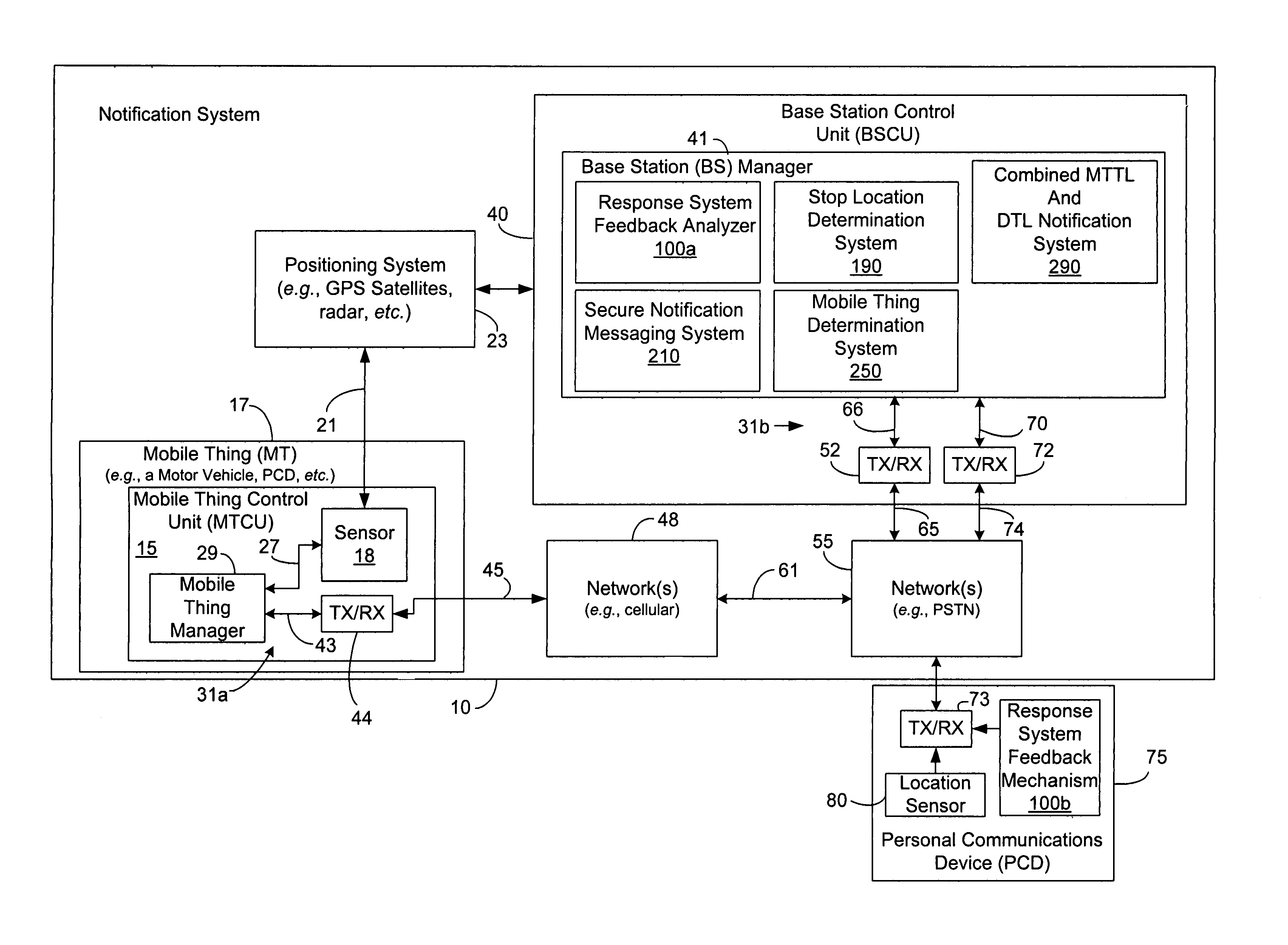
[0243]The response system 100, particularly the response system feedback analyzer 100a, can be configured to implement the following methodology, as is summarized by flow chart in FIG. 7A: causing initiation of or monitoring a notification communication to a PCD 75 associated with a party, as shown in block 101 of FIG. 7A; and during the notification communication, receiving a response from the party via the party's PCD 75, indicating that the party associated with the PCD 75 has received notice, as indicated by block 102 in FIG. 7A. The response can be produced by any system or method that verifies that any party or one or more specific parties received the notification communication. Some such systems and / or methods can accomplish this by verifying or detecting the physical presence of such party(ies) at the PCD 75. Some such systems and / or methods can accomplish this by having the notification-receiving party exercise a physical action that can be convert...
second embodiment
[0257]b. Second Embodiment
[0258]FIG. 7B is a flow chart illustrating another exemplary implementation of a response system feedback analyzer of the present invention, which is optionally implemented as at least part of the architecture, functionality, and operation of the BS manager of FIGS. 1 and 3. In this embodiment, a notified party can cause a connection to be made with a representative that knows the particulars of or that can access the particulars of a pickup or delivery of an item or service in connection with a stop location.
[0259]In this embodiment, the response system 100, particularly the response system feedback analyzer 100a, can be configured to implement the following methodology, as is summarized by flow chart in FIG. 7B: monitoring travel data in connection with an MT 17 that is destined to pickup or deliver (an item or service) at a stop location, as indicated at block 105; causing initiation of a notification communication to a PCD 75 based upon the travel data ...
third embodiment
[0264]. Third Embodiment
[0265]FIG. 7C is a flow chart illustrating yet another exemplary implementation of a response system feedback analyzer of the present invention, which is optionally implemented as at least part of the architecture, functionality, and operation of the BS manager of FIGS. 1 and 3. A response from a notified party is used to change one or more tasks associated with a pickup or delivery of an item or service associated with a stop location.
[0266]In this embodiment, the response system 100, particularly the response system feedback analyzer 100a, can be configured to implement the following methodology, as is summarized by flow chart in FIG. 7C: monitoring travel data in connection with a MT 17 that is destined to pickup or deliver an item or service at a stop location, as indicated at block 108; causing initiation of a notification communication (which may include a message indicating one or more tasks to be accomplished at the stop location) to a personal commun...
PUM
 Abstract
Description
Claims
Application Information
 - R&D
- Intellectual Property
- Life Sciences
- Materials
- Tech Scout
- Unparalleled Data Quality
- Higher Quality Content
- 60% Fewer Hallucinations
Browse by: Latest US Patents, China's latest patents, Technical Efficacy Thesaurus, Application Domain, Technology Topic, Popular Technical Reports.
© 2025 PatSnap. All rights reserved.Legal|Privacy policy|Modern Slavery Act Transparency Statement|Sitemap|About US| Contact US: help@patsnap.com


