Sliding element with keeper device suspended from and guided on a roller rail by support rollers

Inactive Publication Date: 2006-06-27
DORMA GMBH & CO KG
View PDF19 Cites 20 Cited by
  • Summary
  • Abstract
  • Description
  • Claims
  • Application Information

AI Technical Summary

Benefits of technology

[0008]The task of the invention is to provide a keeper device which extends under the roller rail and under the roller rail bracket with very little play—possibly witho

Problems solved by technology

The outer contour of the keeper device which faces the roller rail is only a short distance away from the outer periphery of the roller rail, which means that the sliding element cannot be disengaged from the rail until after the keeper devices have been removed.
If, however,

Method used


Image

  • Sliding element with keeper device suspended from and guided on a roller rail by support rollers
  • Sliding element with keeper device suspended from and guided on a roller rail by support rollers
  • Sliding element with keeper device suspended from and guided on a roller rail by support rollers

Examples


Embodiment Construction

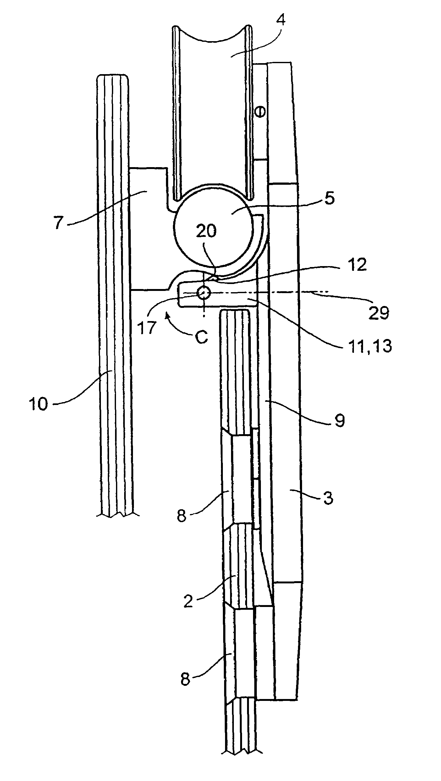
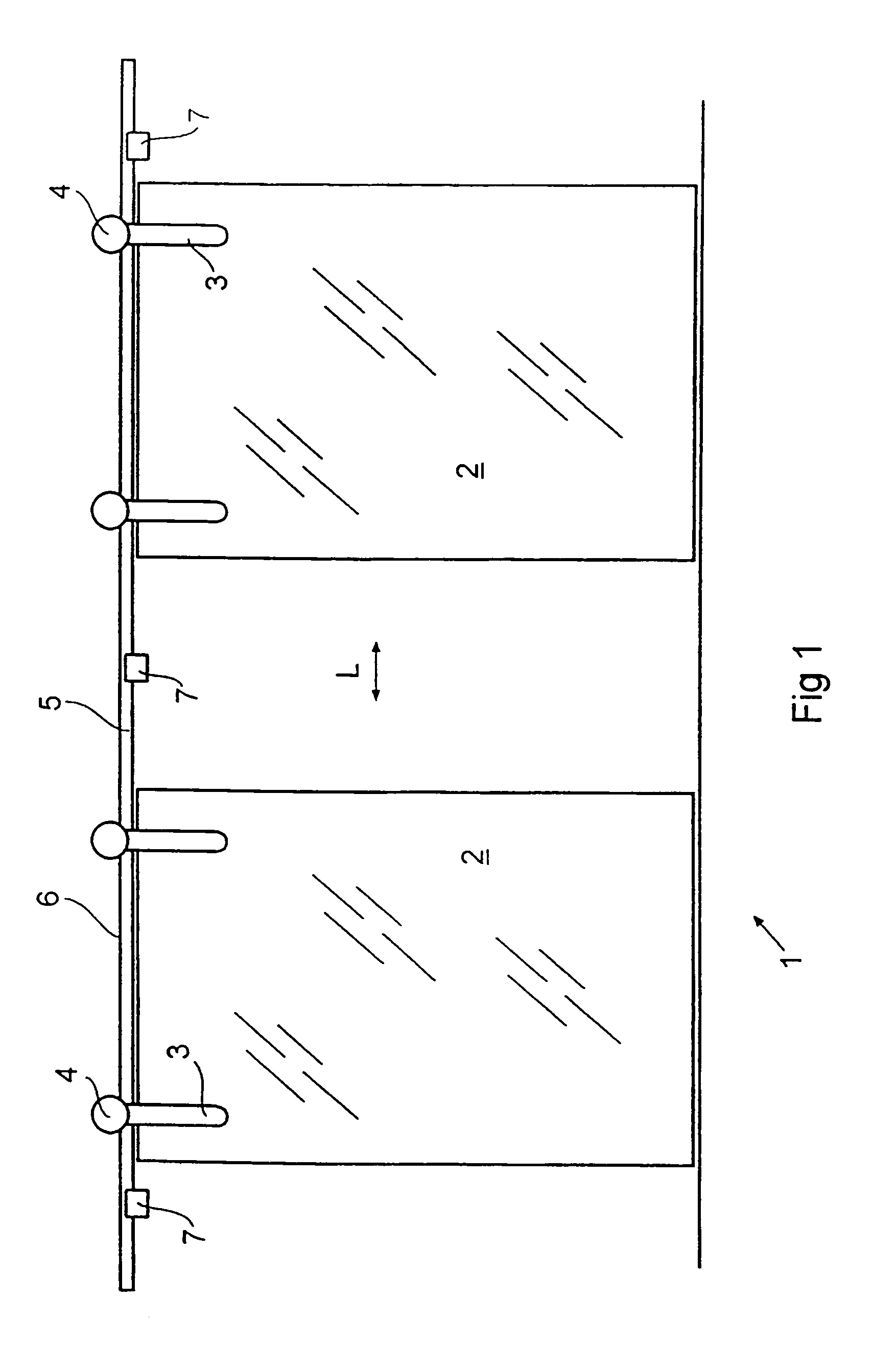
[0029]FIG. 1 shows a glass wall 1, which, in this exemplary embodiment, consists of two sliding elements 2, guided on a roller rail 5. The sliding elements can be moved back and forth in the direction of the arrow L. The sliding elements 2 are suspended from and guided on the top 6 of the roller rail 5 by straps 3 and support rollers 4. The roller rail 5 is attached by roller rail brackets 7 to a substructure (10) (See FIGS. 2 and 3).

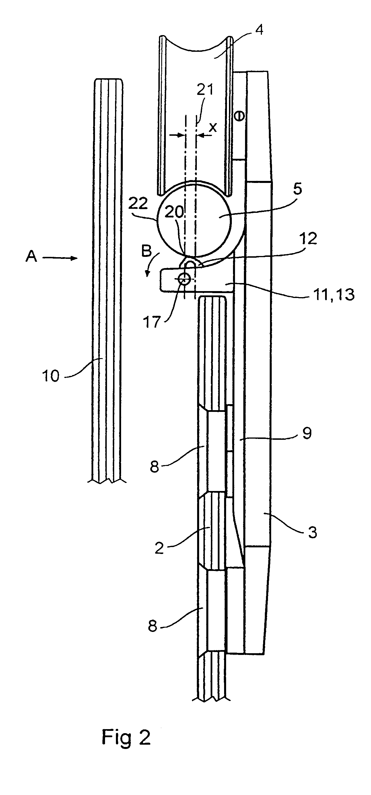
[0030]As can be seen in FIGS. 2 and 3, the straps 3 are connected by point retainers 8 to the sliding element. In the exemplary embodiment, a cover 9, resting on the strap 3, is provided between the strap 3 and the sliding element 2. A keeper device 11 is connected to the strap 3, i.e., to the cover 9, by a screw connection 29. The device has a part called a bracket 13, the top of which (not shown) is hollow like a box, so that a locking element 12 can be supported in this box-like opening. The locking element 12 is pretensioned in the direction of the ...


PUM


Abstract

The invention relates to a sliding element, which is suspended and guided on a running track by means of roller carriers or gliding elements, using running track retainers that are connected to a substructure and engage with the underside of the running track. The invention also relates to an anti-removal device, which comprises a locking elements that can be pressed elastically against the running track and that yields when crossed by a running track retainer.

Description

PRIORITY CLAIM[0001]This is a U.S. national stage of application No. PCT / EP03 / 02796, filed on 18 Mar. 2003. Priority under 35 U.S.C. §119(a) and 35 U.S.C. §365(b) is claimed from German Application No. 102 12 011.0, filed 18 Mar. 26, 2002.BACKGROUND OF THE INVENTION[0002]1. Field of the Invention[0003]The invention pertains to a sliding element suspended from and guided on the top of a roller rail by support rollers or glide elements, where the roller rail is connected to a substructure by roller rail brackets, which grip the roller rail from underneath, and where a keeper device located underneath the roller rail is attached to the sliding element or to components attached to the sliding element.[0004]2. Description of the Related Art[0005]In the usual case, a gap is present between the sliding element and the bottom of the roller rail; this gap is intended to make it possible to hang the sliding element, including its support rollers, as a single unit from the roller rail. During ...

Claims


Application Information

Patent Timeline
IPC IPC(8): A47H15/00E05D15/00E05D15/06
CPCE05D15/0652E05D15/063E05Y2201/614E05Y2201/684E05Y2800/16Y10T16/37E05Y2800/672E05Y2900/132E05Y2600/322Y10T16/364Y10T16/3837E05Y2800/28E05Y2900/00
Inventor ELMER, HUBERT
Owner DORMA GMBH & CO KG
Why Eureka
Try Eureka