Disengagement mechanism for a friction clutch

a technology of friction clutch and disengagement mechanism, which is applied in the direction of friction clutch, interlocking clutch, clutch, etc., can solve the problems of difficult storage of individual parts and assembly

Inactive Publication Date: 2000-08-22
ZF FRIEDRICHSHAFEN AG
View PDF17 Cites 2 Cited by
  • Summary
  • Abstract
  • Description
  • Claims
  • Application Information

AI Technical Summary

Problems solved by technology

This made warehousing of the individual parts and assembly more difficult.
However, this requires separate means for securing or holding the assembly in place during installation.
Furthermo

Method used


Image

  • Disengagement mechanism for a friction clutch
  • Disengagement mechanism for a friction clutch
  • Disengagement mechanism for a friction clutch

Examples


Embodiment Construction

This is an additional application based on the subject matter in U.S. patent application Ser. No. 08 / 821,772, which is incorporated herein by reference in its entirety.

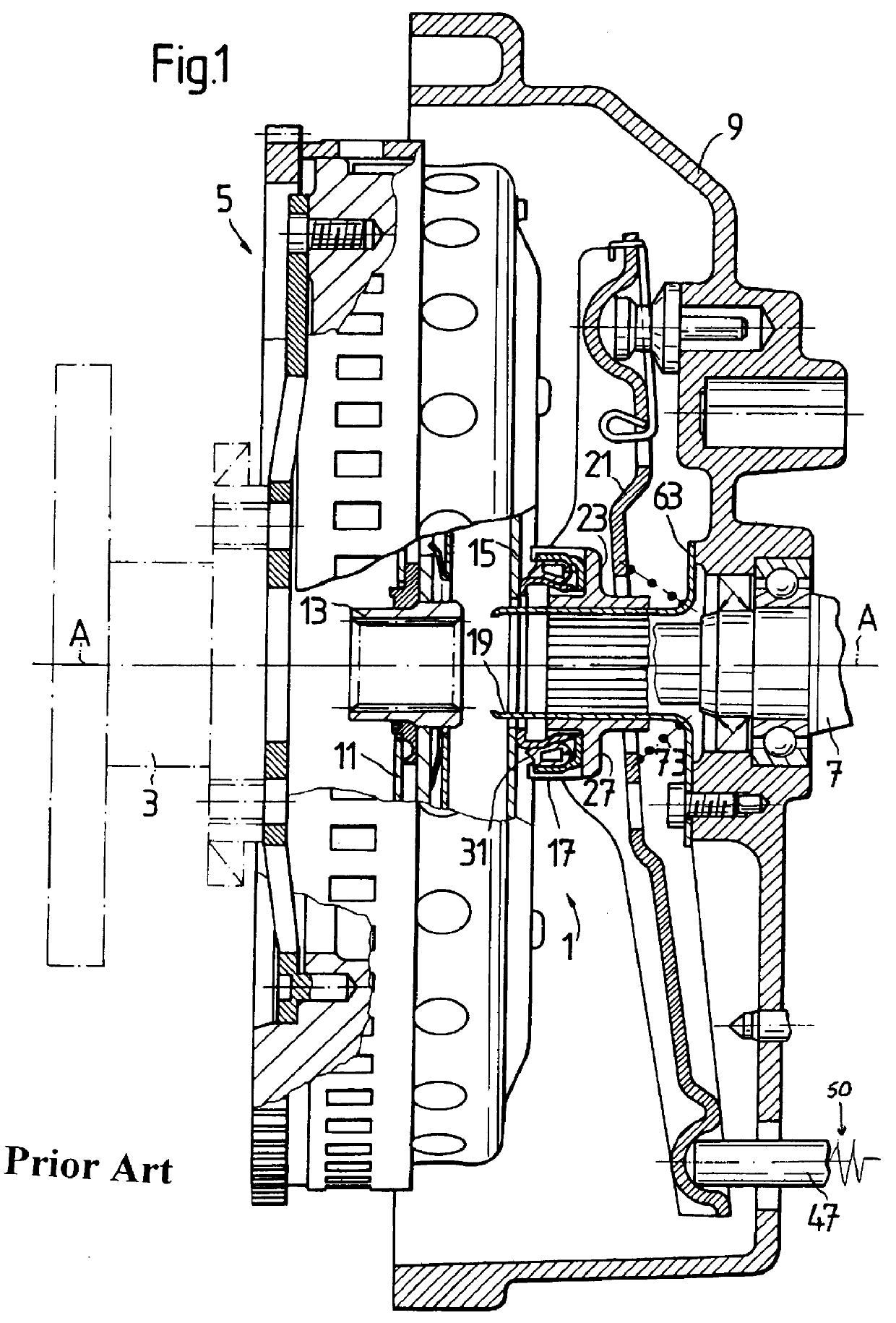
Referring initially to FIG. 1, a partial axial longitudinal view through the embodiment of a disengagement mechanism 1 for a friction clutch 5 disclosed in U.S. patent application Ser. No. 08 / 821,772 is shown. The friction clutch 5 is arranged at the end of a crankshaft 3 of an internal combustion engine for transmitting torque from the crankshaft 3 to an input shaft 7 of a transmission arranged following the internal combustion engine. The crankshaft 3, clutch 5 and input shaft 7 are arranged in this order one behind the other coaxially along a common axis of rotation A--A. The transmission is flanged to the internal combustion engine by a casing 9 formed on at the transmission housing. The disengagement mechanism 1 is arranged axially between the clutch 5 and the casing 9.

The clutch 5 includes a clutch disk 11 which...


PUM


Abstract

A disengagement mechanism for a friction clutch which is to be arranged between an internal combustion engine and a transmission flanged to the internal combustion engine by a casing includes a guide pipe fastenable in the casing. A release bearing element is guided radially at the outer circumference of the guide pipe so as to be axially movable thereon. The disengagement mechanism also includes a clutch lever which is to be articulated at the casing for transmitting clutch actuating forces to the release bearing element. At least the guide pipe, the release bearing, and the clutch lever are held together to form a constructional unit prior to their arrangement between the internal combustion engine and the transmission by movement limiting device, thereby facilitating the assembly of the disengagement mechanism. In the operation-ready, installed state, the movement limiting devices influences the movability of the disengagement mechanism.

Description

1. Field of the InventionThe present invention relates to a disengagement mechanism for a friction clutch in a motor vehicle, wherein the friction clutch is arranged between an internal combustion engine and a transmission connected to the internal combustion engine by a casing and the friction clutch is rotatable about an axis.2. Description of the Related ArtGerman reference DE-OS 23 22 247 discloses a self-centering release bearing which is held in frictional contact at a clutch lever so as to be displaceable radially by a plurality of spring clamps. The spring clamps also fix a guide sleeve which slides on a guide pipe between the release bearing and the clutch lever.British reference GB-2 046 359 A discloses a release bearing whose guide sleeve can be snapped onto a release lever when installed in the vehicle by locking pins which are formed integral with the guide sleeve.French reference FR-2 577 291 discloses a self-centering release bearing arrangement in which the release b...

Claims


Application Information

Patent Timeline
IPC IPC(8): F16D23/00F16D23/12
CPCF16D23/12F16D2300/12
Inventor HUSSE, ULRICHLINDNER, KURTMULLER, KARLVOSS, REINERWALTER, THOMAS
Owner ZF FRIEDRICHSHAFEN AG
Why Eureka
Try Eureka