Handheld power tool

a power tool and hand-held technology, applied in the direction of wrenches, screwdrivers, clutches, etc., can solve the problems of electrical signals generated, and achieve the effect of simple and rapid manner

Active Publication Date: 2018-09-27
ROBERT BOSCH GMBH
View PDF10 Cites 2 Cited by
  • Summary
  • Abstract
  • Description
  • Claims
  • Application Information

AI Technical Summary

Benefits of technology

[0021]An optical sensor, in particular, a photoelectric barrier, especially, a photoelectric reader, is particularly advan

Problems solved by technology

A disadvantage is that due to the elasticity of the component parts used, in response to unfavorable working situations in which loads and vibrations sudden

Method used


Image

  • Handheld power tool
  • Handheld power tool
  • Handheld power tool

Examples


Embodiment Construction

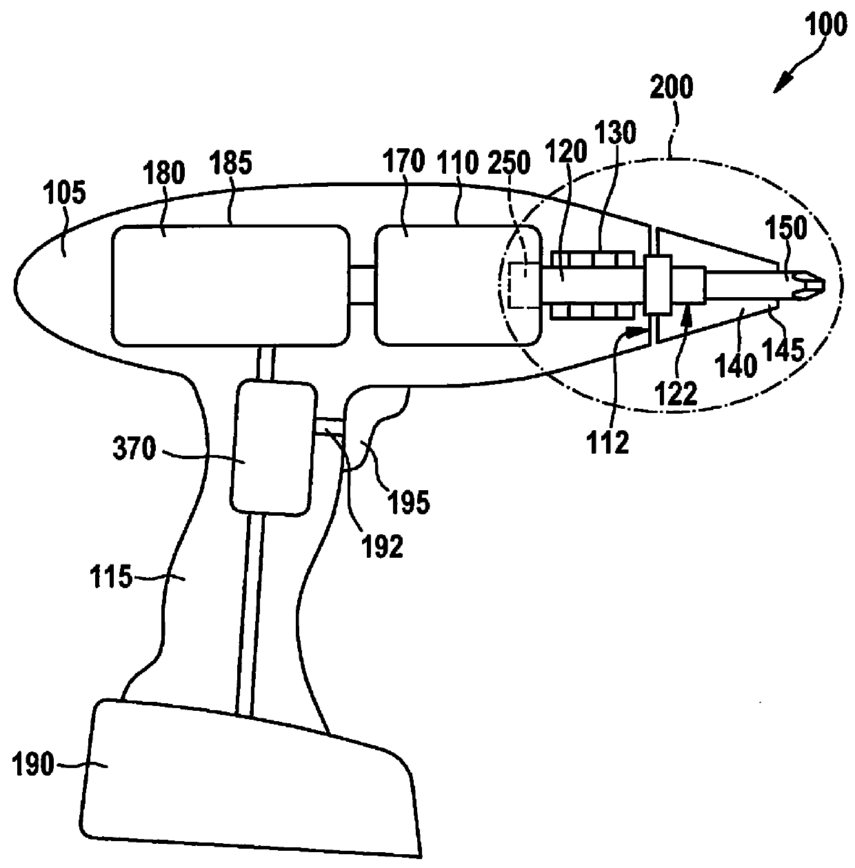
[0032]FIG. 1 shows a handheld power tool 100 of the present invention, which includes a housing 105 having a handle 115. According to the specific embodiment depicted, handheld power tool 100 is mechanically and electrically connectible to a battery pack 190, in order to supply power independently of an electrical network. In FIG. 1, handheld power tool 100 illustratively takes the form of a cordless drill / driver. However, it is emphasized that the present invention is not limited to cordless drill / drivers, but on the contrary, may be applicable to different handheld power tools, in which a tool is set into rotation, for example, to a cordless drill, a cordless impact drill, or a straight screwdriver or an impact drill, etc.

[0033]An electric drive motor 180 powered by current from battery pack 190, and a gear unit 170, are situated in housing 105. Drive motor 180 is connected to a drive shaft 120 via gear unit 170. For the purpose of illustration, drive motor 180 is situated in a mo...


PUM


Abstract

A handheld power tool includes a torque coupling adjustable by the operator, as well as a gear unit for transmitting a torque generated by a drive motor to a drive shaft. The gear unit is advantageously a planetary gear unit; the torque coupling being constructed in such a manner, that in response to slippage of the torque coupling, a coupling component follows a displacement path. The handheld power tool further includes a control unit and a sensor, the sensor monitoring the coupling component for a displacement and transmitting corresponding sensor signals to the control unit. The control unit is configured to control, in particular, switch off, the drive motor as a function of the sensor signals received. It is further provided that the control unit subject the received sensor signals to a plausibility check, in order to determine if actual slippage of the torque coupling is occurring.

Description

FIELD[0001]The present invention relates to a handheld power tool, in particular, a screwdriver, a drill / driver or a cordless drill / driver, including a rotatable tool support, which may be driven via a gear unit.BACKGROUND INFORMATION[0002]Handheld power tools having a gear unit, in particular, a planetary gear unit, such as a straight screwdriver, a cordless drill / driver or a drill, include, generally, a safety coupling adjustable by the operator, so that the handheld power tool does not continue to rotate uncontrollably in response to a predetermined torque being exceeded. Thus, German Patent Application No. DE 197 37 234 A1 describes a tool having a rotatable tool support, the tool support being drivable by a drive motor via a planetary gear unit, and the ring gear of the planetary gear unit interacting with the gear housing via a slip clutch in such a manner, that a pressure plate moves away from the clutch upon the reaching of an adjustable torque, which means that a movement o...

Claims


Application Information

Patent Timeline
IPC IPC(8): B25F5/00B25B23/14B25B23/147F16D7/00F16D43/02
CPCB25F5/001B25B23/141B25B23/147F16D7/005F16D43/02B25B21/00F16D2300/18
Inventor HECHT, JOACHIMHOPP, MICHAEL
Owner ROBERT BOSCH GMBH
Why Eureka
Try Eureka