Planetary gear

a technology of planetary gear and gear shaft, which is applied in the direction of gear, manufacturing tools, transportation and packaging, etc., can solve the problems of negative influence on the working surface, unbalance equal to 160 g-mm, extreme vibration,

Active Publication Date: 2007-05-03
ZF FRIEDRICHSHAFEN AG
View PDF7 Cites 1 Cited by
  • Summary
  • Abstract
  • Description
  • Claims
  • Application Information

AI Technical Summary

Benefits of technology

[0013] This so-called “captive” sliding collar, which in the first operating position is placed over the hub's centering collar, exhibits the benefit that the sliding collar in this operating position has significantly smaller play between the hub and the sliding collar than in common planetary transmissions, which merely exists from the play between the centering bore and the centering collar. The present function namely produces a positive fit connection between the sliding collar and the hub.
[0014] In a further embodiment of the invention, the sliding collar bearing will be fixed in the axial direction with a shrunken holding ring. This offers the advantage that no additional unbalancing is produced.
[0016] This offers the additional benefit that also with a small disalignment of the sliding collar to the hub, the centering bore can run with no problems from the centering collar.

Problems solved by technology

The planetary transmission, which is a part of the machine tool transmission, is therefore a potential source of vibration that when the rotational speed increases can negatively influence the working surface.
The clearance in turn leads to an nonconcentric rotation, which generates unbalancing.
For example, a sliding collar with the common weight of 1.6 kg can only move 0.1 mm from the center position, therefore the resulting unbalance is equal to 160 g-mm, which generates an extreme vibration.
A planetary transmission operating under high rotational speed (i=1:1) demands a detailed processing of the work piece surface, which can only be achieved with low vibration machine tools.

Method used


Image

  • Planetary gear
  • Planetary gear

Examples


Embodiment Construction

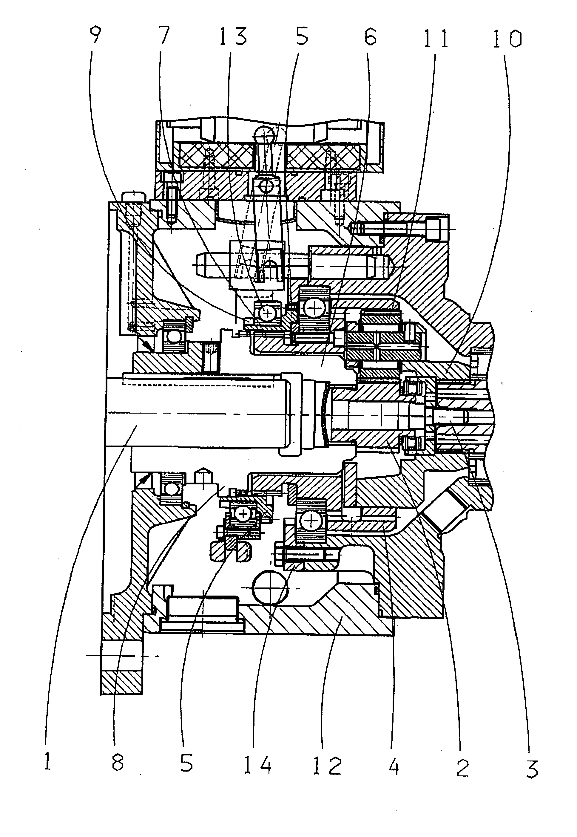
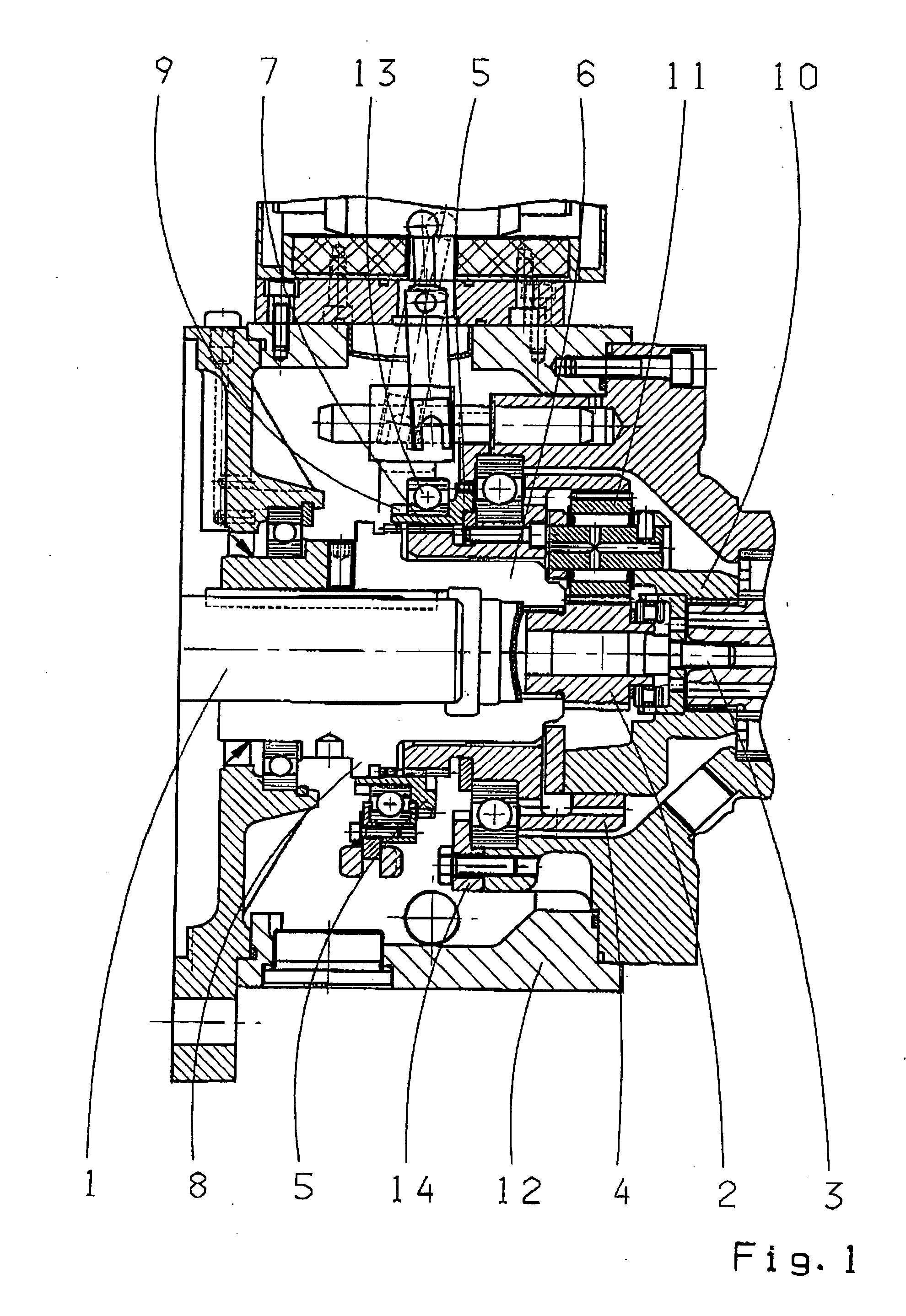
[0019] The planetary transmission shows a drive shaft 1 which is connected to a sun gear 2, as well as an output shaft 3 which is connected to a planetary carrier 10, whereby one of the planetary gears is identified with number 11. It further shows an internal gear 4, that in its first operating position engages with housing 12 of the planetary transmission, and in its second operating position engages with sun gear 2 aided by hub 6. Hub 6 concentrically surrounds drive shaft 1. The sliding collar is identified with number 5, which actuates the switch between both operating positions. Sliding collar 5 is thereby axially and movably mounted in bearings over internal gear 4.

[0020] In the upper half of the single FIGURE, the sliding collar 5 is shown engaged with the braking disc 14, whereby this operating position corresponds to the i>1 transformation of the two-stage planetary transmission.

[0021] According to the invention, the sliding collar 5 is intended to be placed in the loose...


PUM

PropertyMeasurementUnit
weightaaaaaaaaaa
diameteraaaaaaaaaa
displacementaaaaaaaaaa

Abstract

A planetary transmission, in particular for machine tools, with a drive shaft that is connected to a sun gear, with an output shaft that is connected to a planetary carrier and with an interior gear, that in a first operating position engages with the housing, and in the second operating position engages with the sun gear, with a hub that surrounds the drive shaft concentrically and with a sliding collar that surrounds the hub concentrically and that engages with the hub in an operating position. The sliding collar (5) engages in the loose end of the interior gear (4) with a centering diameter (7) concentrically located with the hub (6), which in the engaged position of the sliding collar (5) engages with the hub (6) in a concentric position with the hub's axle on its centering collar (8).

Description

[0001] This application is a national stage completion of PCT / EP2004 / 010883 filed Sep. 29, 2004 which claims priority from German Applications Serial Nos. 10 2004 003 685.3 filed Jan. 24, 2004, 10 2004 003 684.5 filed Jan. 24, 2004, 103 48 757.3 filed Oct. 21, 2003 and 103 48 755.7 filed Oct. 21, 2003.FIELD OF THE INVENTION [0002] The present invention refers to a planetary transmission, in particular for machine tools. BACKGROUND OF THE INVENTION [0003] This planetary transmission, mostly built as a single- or multiple-stage planetary transmission, is basically implemented in machine tools, as well as in lathes, milling machines and machining centers. The selectable planetary transmission increases the service scope of the main spindle motors, as well as the flexibility of the machine tool for processing the different work materials through increasing high torques or high speeds. For example, two transmission stages may be built in, while on one hand the drive shaft which is connec...

Claims


Application Information

Patent Timeline
Patent Type & Authority Applications(United States)
IPC IPC(8): F16H3/44B23Q1/00F16H3/54F16H57/04
CPCB23Q1/0036F16H3/54F16H57/04Y10T409/309352Y10T409/309464Y10T408/45Y10T408/91F16H2200/0034F16H3/44
Inventor ECKERT, HARALDKUCHELMEISTER, ULRICHFORSTER, ECKHARD
Owner ZF FRIEDRICHSHAFEN AG
Why Eureka
Try Eureka