Controlled engine camshaft stopping position

a technology of camshaft and camshaft, which is applied in the direction of engine starters, electrical control, valve arrangements, etc., can solve the problems of excessive engine wear, deflated hvl noise, and overall size of lifters, and achieve the effect of reducing cold start nois

Inactive Publication Date: 2006-06-27
DELPHI TECH INC
View PDF5 Cites 14 Cited by
  • Summary
  • Abstract
  • Description
  • Claims
  • Application Information

AI Technical Summary

Problems solved by technology

When the engine is restarted, the piston chamber will be refilled as engine control is re-established and the engine oil supply pressure increases, but for the first few seconds of operation, the deflated HVL can be objectionably noisy (known in the art as “cold start noise”) and can also cause excessive engine wear.
This problem is aggravated by the trend in the HVL art to smaller piston chambers, having lower reservoir volumes, to reduce the overall size of the lifters.
In addition, special HVLs for use in valve deactivation on some engines have especially small piston chambers and are therefore especially vulnerable to leakdown under stopped, valve-open load.

Method used


Image

  • Controlled engine camshaft stopping position
  • Controlled engine camshaft stopping position
  • Controlled engine camshaft stopping position

Examples


Embodiment Construction

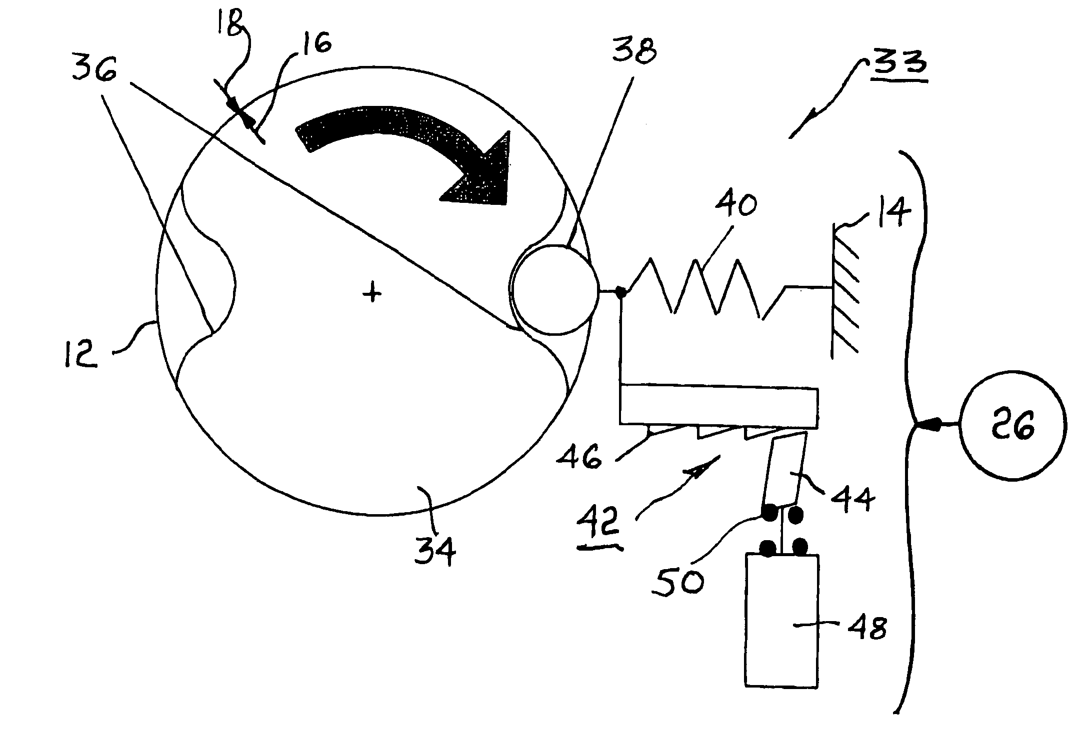
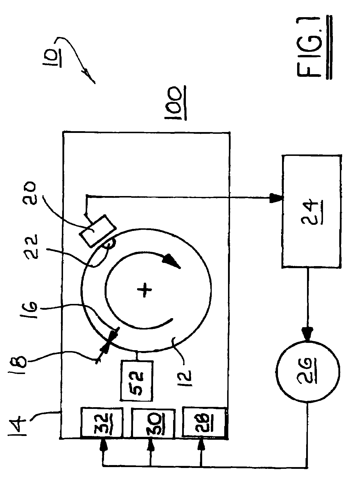
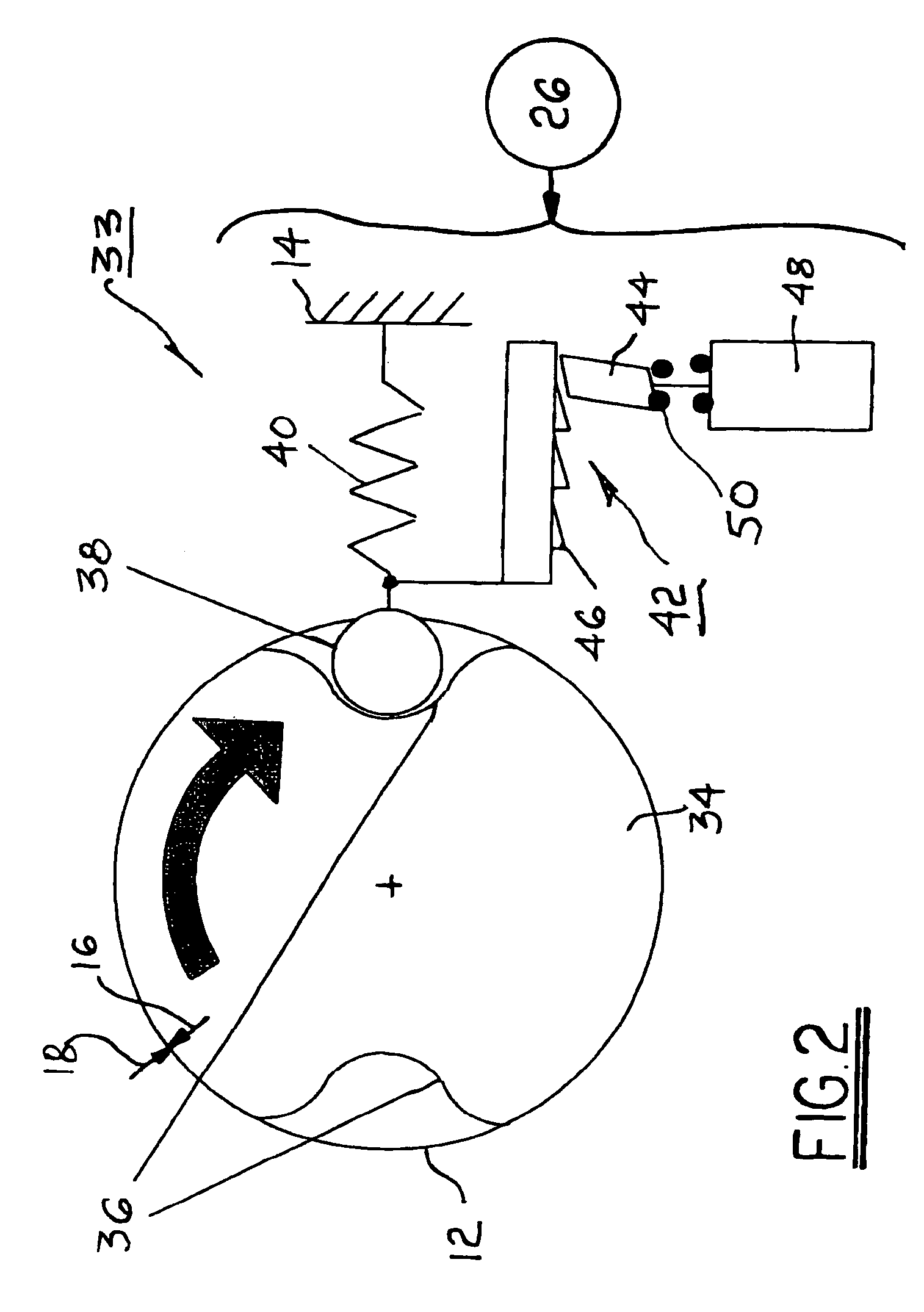
[0018]Referring to FIG. 1, a system 10 is shown for positioning an engine shaft 12, such as a crankshaft or a camshaft of an internal combustion engine 14 at a predetermined rotational position 16 of the camshaft with respect to a position 18 of the engine (and in particular, the engine's valves operated by the camshaft) when the engine stops rotation after being shut down. A shaft position sensor 20 monitors the rotary position of a target 22 on the shaft and sends that information to a programmable electronic engine control module (ECM) 24. ECM 24 is programmed such that, during stopping of engine 14, ECM 24 engages and controls shaft positioning mechanism 26 to cause shaft position 16 to stop opposite engine position 18.

[0019]In a first exemplary embodiment, as engine 14 is shut down and shaft 12 comes to rest, its angular position is known as determined by sensor 20 and target 22. If the position is as desired (position 16 corresponds to position 18, defining a correct stopping ...


PUM


Abstract

A system for bringing an internal combustion engine to a stop at a predetermined angular position of an engine shaft, such as a crankshaft or a camshaft, with respect to the engine's valves. The optimum shaft stop position is the point wherein the fewest lifters are collapsed the least amount. Exemplary methods and apparatus include using the engine starter motor to jog the stopped engine to the desired position; using the engine alternator to impose a variable electromagnetic load on the engine to bring the engine to a stop at the desired position; using variable firing of cylinders to control the deceleration profile to bring the engine to a stop at the desired position; and providing one or more detents formed in the shaft and using a shaft follower to control the stop position of the shaft by engaging the follower into a detent.

Description

TECHNICAL FIELD[0001]The present invention relates to internal combustion engines; more particularly, to camshafts or crankshafts in internal combustion engines; and most particularly, to a method and apparatus for stopping the shaft at a predetermined angular position when the engine is shut off.BACKGROUND OF THE INVENTION[0002]Internal combustion engines having intake and exhaust valves are well known. A typical internal combustion engine includes at least one camshaft having lobes for opening and closing the valves. In some engines, separate camshafts are provided for the intake and exhaust valves; thus each of the twin camshafts has only half of the total number of cam lobes.[0003]In modern internal combustion engines, each valve train typically includes a hydraulic valve lifter (HVL) for automatically eliminating mechanical lash in the valve actuating mechanism. A spring urges a piston outwards to eliminate lash, and in response the piston chamber fills with oil via a check val...

Claims


Application Information

Patent Timeline
Patent Type & Authority Patents(United States)
IPC IPC(8): F02D45/00F02N99/00
CPCF01L1/047F01L1/46F02B77/08F02D41/042F01L1/24F02N2019/008F01L2800/03F01L2820/041F01L2820/042F02D2041/001F02D2041/0095F02N11/00F02N11/04F02N19/004F02N19/005F01L2810/04
Inventor FLANAGAN, JASON W.KUNZ, TIMOTHY W.HARRIS, WAYNE S.FISCHER, THOMAS H.
Owner DELPHI TECH INC
Why Eureka
Try Eureka