Extensible brake wear gauge

a technology of wear gauges and brakes, applied in the direction of brake types, mechanical equipment, etc., can solve the problems of uniform deficiency in providing the service of the brakes

Active Publication Date: 2006-06-27
TALBERT CHRISTOPHER M
View PDF8 Cites 5 Cited by
  • Summary
  • Abstract
  • Description
  • Claims
  • Application Information

AI Technical Summary

Benefits of technology

[0010]As will be explained in greater detail further on in the specification, the wear gauge plate is disposed in a perpendicular orientation to the distal end of the telescoping support rod and further provided with different colored segments representative of minimal wear, extensive wear and excessive wear.
[0011]The telescoping support rod in conjunction with the illumination member assists the user in positioning the wear gauge plate behind the pin of a boss and pin wear indicator so that the person utilizing the brake wear gauge of this invention will be able to make a quick visual determination as to the level of brake lining wear that is represented by the pin wear indicator.

Problems solved by technology

While all of the aforementioned prior art constructions are more than adequate for the basic purpose and function for which they have been specifically designed, they are uniformly deficient with respect to their failure to provide a simple, efficient, and practical brake wear gauge that is particularly suitable for relatively inaccessible locations to quickly and easily determine brake lining wear on pneumatic disc brake systems that utilize a conventional boss and pin measurement for assessing the extent of brake lining wear.

Method used


Image

  • Extensible brake wear gauge
  • Extensible brake wear gauge

Examples


Embodiment Construction

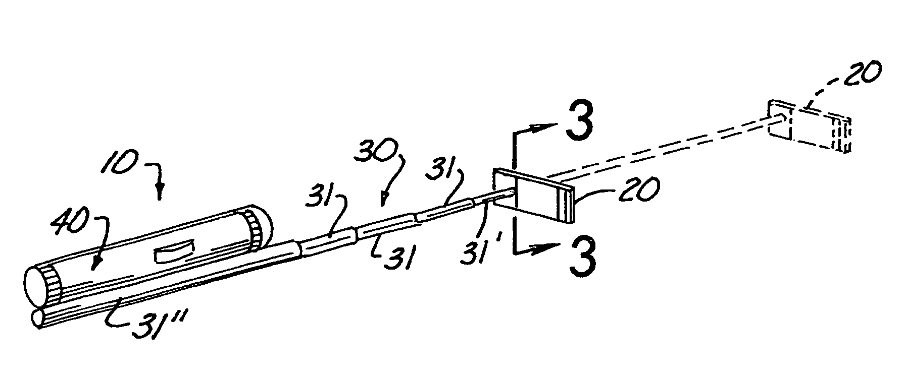
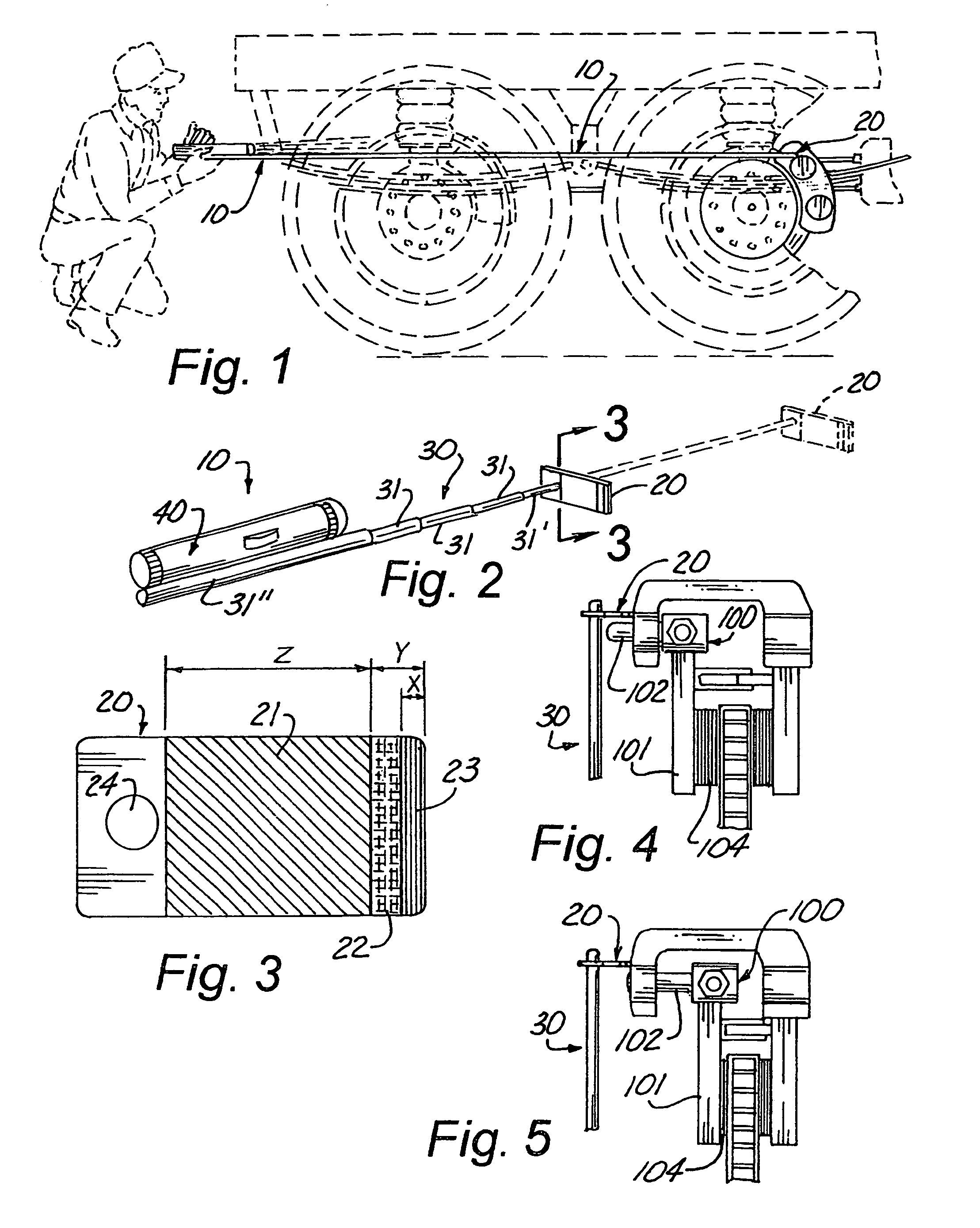
[0018]As can be seen by reference to the drawings, and in particular to FIGS. 1 and 2, the extensible brake wear gauge device that forms the basis of the present invention is designated generally by the reference number 10. The device 10 comprises in general a wear indicator plate 20, a telescoping support shaft member 30 and an illumination member 40 which will now be described in seriatim fashion.

[0019]Turning now to FIG. 3, it can be seen that the wear plate member 20 has a generally flat elongated rectangular configuration and is provided with a plurality of differently colored wear indicator segments 212223 colored green, yellow and red respectively wherein, the green wear indicator segment 21 occupies the intermediate portion of the inboard face of the plate member 20 and represents minimal to acceptable brake lining wear.

[0020]In addition, the distal end of the inboard face of the wear plate member 20 is occupied by a relatively narrow red wear indicator segment 23 that repre...


PUM


Abstract

A wear gauge device (10) for use with disc brake systems having a boss (100) provided with a floating arm (101) and wear indicator pin (102) that track the thickness of brake lining material (104) wherein, the wear gauge device (10) includes an illumination member (40) mounted on one end of a telescoping support member (30) the other end of which is connected and disposed perpendicular to a wear plate member (20) having a plurality of different colored wear indicator segments (21) (22) (23) that are positionable behind the wear indicator pin (102) to obtain an estimate of the remaining amount of brake lining material (104).

Description

BACKGROUND OF THE INVENTIONCross Reference to Related Applications[0001]Not applicable.[0002]1. Field of the Invention[0003]The present invention relates to the field of brake wear gauge constructions in general and in particular to a brake wear gauge specifically designed for relatively inaccessible locations.[0004]2. Description of Related Art[0005]As can be seen by reference to the following U.S. Pat. Nos. 6,237,723; 3,854,216; 5,535,854; 4,594,785; and, 3,660,905, the prior art is replete with myriad and diverse arrangements for determining the wear on brake pads and the like.[0006]While all of the aforementioned prior art constructions are more than adequate for the basic purpose and function for which they have been specifically designed, they are uniformly deficient with respect to their failure to provide a simple, efficient, and practical brake wear gauge that is particularly suitable for relatively inaccessible locations to quickly and easily determine brake lining wear on...

Claims


Application Information

Patent Timeline
Patent Type & Authority Patents(United States)
IPC IPC(8): F16D66/02
CPCF16D66/02
Inventor TALBERT, CHRISTOPHER M.
Owner TALBERT CHRISTOPHER M
Why Eureka
Try Eureka