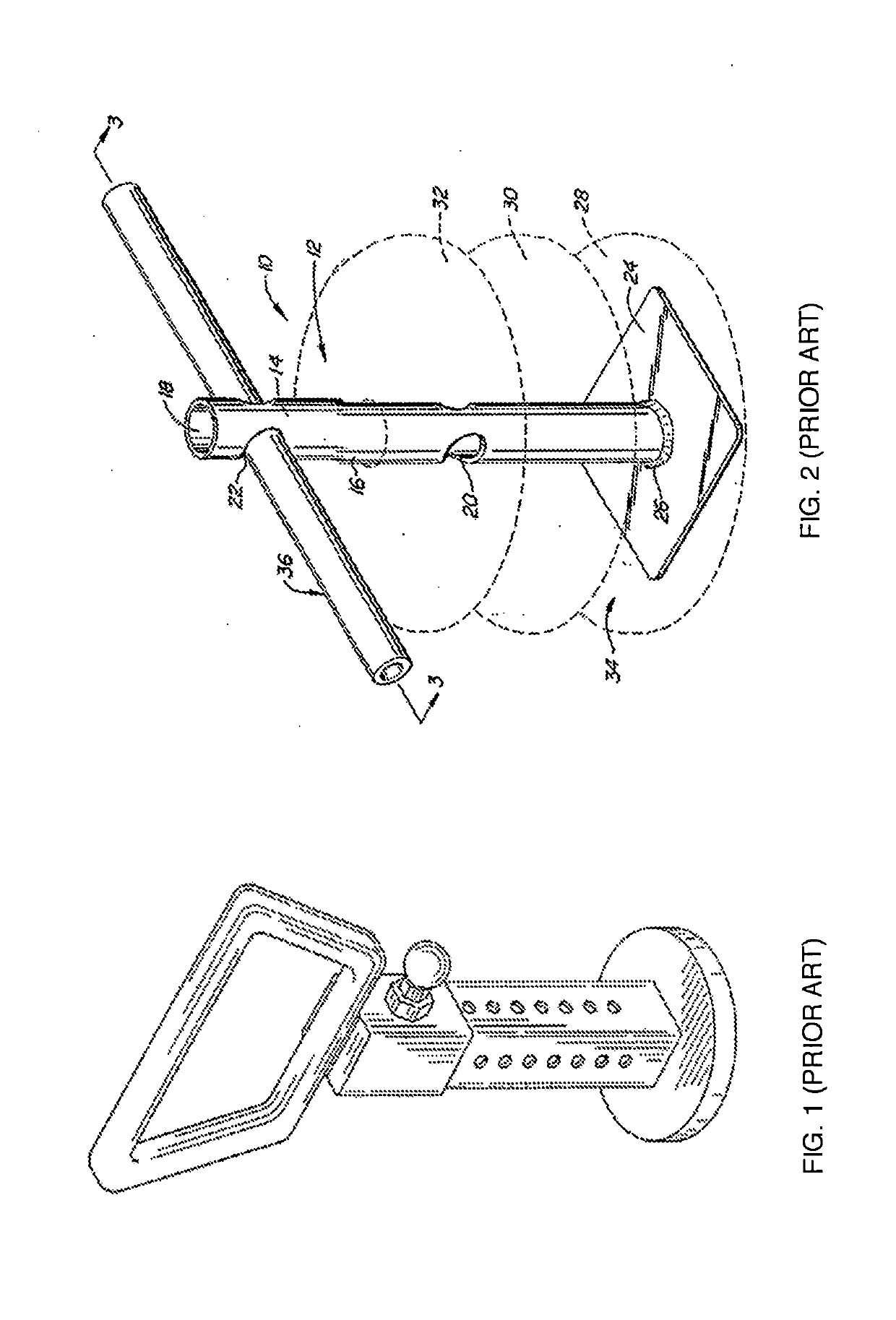
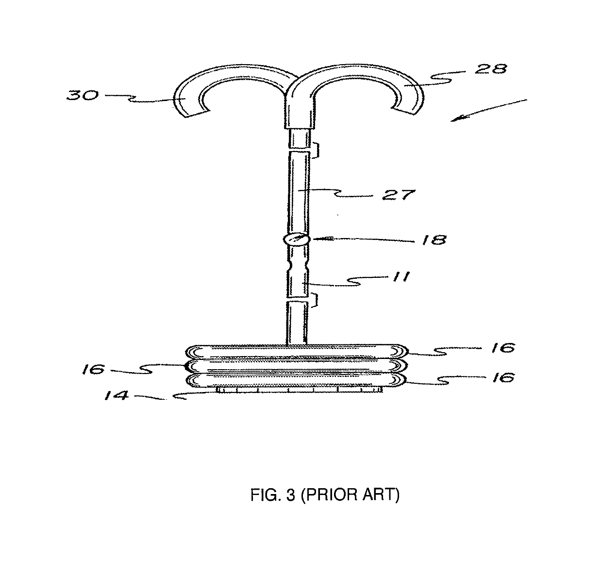
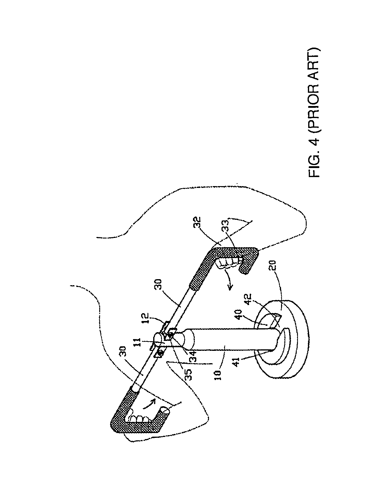
Deadlift bar apparatus and method

a bar apparatus and bar technology, applied in sport apparatus, weights, gymnastics, etc., can solve the problems of heavy lifting, difficult to perform with proper form, and heavy lifting, and achieve the effect of reducing wear and large diameter

Inactive Publication Date: 2019-09-19
ACUNA JR ROBERTO
View PDF0 Cites 10 Cited by
  • Summary
  • Abstract
  • Description
  • Claims
  • Application Information

AI Technical Summary

Benefits of technology

[0029]In one embodiment, an improved deadlift device includes a cylindrical shaft having a lower end threaded onto a base. The cylindrical shaft is configured to accept one or more weights to be inserted onto the shaft and resting on the base. The cylindrical shaft has a plurality of horizontal channels, where each channel has a main horizontal through hole with a downwardly extending keyhole slot extension. Both the main holes and the keyhole slots have beveled edges so that portions of one or more resistance bands may be routed through the keyhole slots and used with minimal wear. The main holes have a slightly larger diameter than the diameter of a removable elongated bar which may be inserted into any of the channels. In one example, the elongated bar has a length of approximately 10 inches or less so that the device may be used for kettlebell swing exercises. In other examples, the elongated bar is longer so that the user may grasp the bar with hands spaced below the user's shoulders.

Problems solved by technology

A deadlift, whether it is sumo style, conventional style, or Romanian style, is hard to perform with proper form.
This lift can cause the user serious injury if not performed properly, due to all the steps needed to ensure the lift is done correctly.
Using a straight barbell to perform the deadlift can be too big and heavy for new lifters.
Also, when using a straight barbell correctly for the deadlift; it can result in scraping the skin off the shins and thighs of the lifters.

Method used


Image

  • Deadlift bar apparatus and method
  • Deadlift bar apparatus and method
  • Deadlift bar apparatus and method

Examples


Embodiment Construction

[0072]The following element list is provided for convenience in reviewing the figures:[0073]user 50[0074]head 51[0075]shoulders 52, 53[0076]back 54[0077]spine 56[0078]arms 58, 59[0079]hands 63, 64[0080]feet 70, 71[0081]Weights 60, 61, 62,[0082]Deadlift device 100, 101, 102[0083]Base 120[0084]floor protector 122[0085]central recess 123[0086]shaft attachment threads 124[0087]shaft weld 126 (not shown)[0088]interchangeable base 128[0089]shaft connection bolt 129[0090]main shaft 130[0091]handle mounting pin holes 131A, 131B, 131C[0092]external diameter 132[0093]top portion of shaft 140[0094]top of shaft 142[0095]rounded top 144[0096]bottom portion of shaft 150[0097]bottom of shaft 152[0098]base attachment threads 154[0099]overlapping thread lip locking element 156[0100]rubber pad 158[0101]first channel 160[0102]bottom portion of hole 161[0103]main through-hole 162[0104]beveled edge 163[0105]keyway slot 164[0106]beveled edge 165[0107]second channel 170[0108]bottom portion of hole 171[010...


PUM


Abstract

A deadlift device includes a cylindrical shaft attached to a base with a selectable weight. Horizontal channels in the shaft have a main horizontal through hole with a downwardly extending keyhole slot extension with beveled edges, so that portions of one or more resistance bands may be routed through the keyhole slots and used with minimal wear. A removable Y-lift bar with right and left hand vertical upper portion and diagonal lower portion which may be attached at any of the channels. An alternative removable short horizontal bar may be inserted at at any of the channels to permit kettlebell swing exercises. The device may be used effectively with a range of lift and walking exercises using the deadlift device with added weights and/or one or more resistance bands.

Description

RELATED APPLICATIONS[0001]This U.S. non-provisional application is a continuation in part of U.S. patent application Ser. No. 15 / 386,312 filed by applicant on Dec. 21, 2016, which is related to US Provisional Application No. 62 / 383,220 filed by applicant on Sep. 2, 2016, and claims the benefit of that provisional application filing date.BACKGROUND—FIELD OF THE INVENTION[0002]The current invention relates to an improved weight lifting device, and more particularly to an improved deadlift device and method of use.BACKGROUND—PRIOR ART[0003]The deadlift is a key exercise in strength and conditioning programs. There are several deadlift variations, classifiable by the type of barbell used; and the technique used (sumo, conventional, stiff-legged, Romanian). The deadlift involves greater upper lumbar erector spinae muscle activity, but less lower lumbar erector spinae muscle activity than the back squat. It involves similar abdominal muscle activity to the back squat, side plank and super...

Claims


Application Information

Patent Timeline
Patent Type & Authority Applications(United States)
IPC IPC(8): A63B21/072A63B21/00A63B21/055
CPCA63B21/0552A63B21/0724A63B21/0004A63B21/4035A63B21/0728A63B21/00065A63B21/068A63B21/0557A63B23/1218A63B23/03525A63B2225/09A63B2210/50
Inventor ACUNA, JR., ROBERTO
Owner ACUNA JR ROBERTO
Why Eureka
Try Eureka