Sliding contact guide for transmission device

a contact guide and transmission device technology, applied in the direction of belts/chains/gearrings, mechanical equipment, etc., can solve the problems of difficult control of the finished product size, difficult to remove heat from the central portion of the chain contact surface during molding, and prone to deformation, so as to achieve uniform cooling, suppress deformation of the shoe due to thermal shrinkage following molding, and adequate strength

Active Publication Date: 2011-08-30
TSUBAKIMOTO CHAIN CO
View PDF6 Cites 13 Cited by
  • Summary
  • Abstract
  • Description
  • Claims
  • Application Information

AI Technical Summary

Benefits of technology

[0011]The spaced, longitudinal ribs, which preferably extend along the sides of the shoe, allow uniform cooling during thermal shrinkage. The ribs of the lattice formed between the longitudinal ribs ensure that the guide has adequate strength to serve as a sliding contact guide for a travelling transmission medium. Moreover, since the widths of the longitudinal ribs are greater than the widths of the lattice ribs, deformation of the shoe due to thermal shrinkage following molding is suppressed.
[0012]Suppression of thermal shrinkage after molding affords a greater degree of freedom in the design of the shoe, and reduces the size variation of the finished product so that consistent high quality can be achieved. Suppression of thermal shrinkage of the shoe also reduces deformation of the sliding contact surface, so that a chain or other traveling transmission medium can run over the shoe in a stable manner with a minimum of wear. As a result, the service life of the shoe is extended.BRIEF DESCRIPTION OF THE DRAWINGS

Problems solved by technology

In the conventional resin shoe of the kind depicted in FIG. 4, it is difficult to remove heat from the central portion of a chain-contacting surface during molding.
Consequently, deformation is liable to occur as a result of thermal shrinkage and warping following molding.
Another problem encountered in the molding of the conventional shoes is that the size of the finished product is difficult to control, and consequently significant size variations have been observed.

Method used


Image

  • Sliding contact guide for transmission device
  • Sliding contact guide for transmission device
  • Sliding contact guide for transmission device

Examples


Embodiment Construction

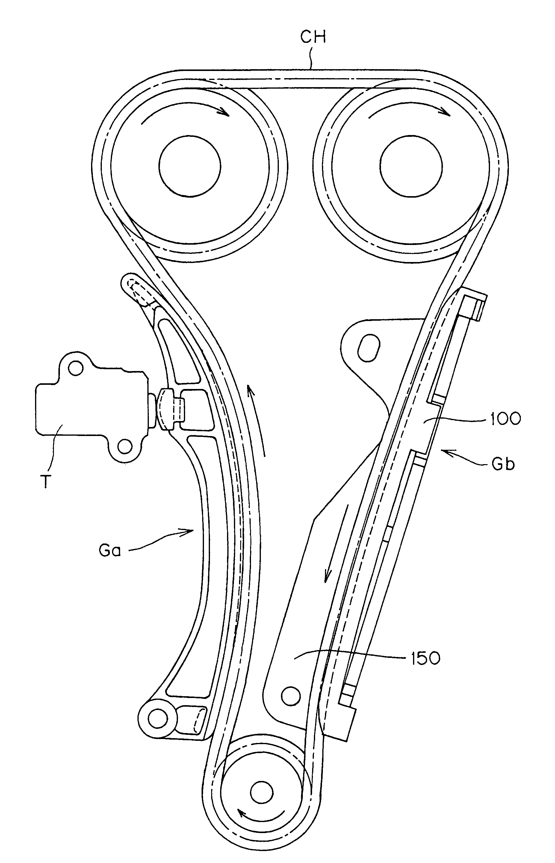
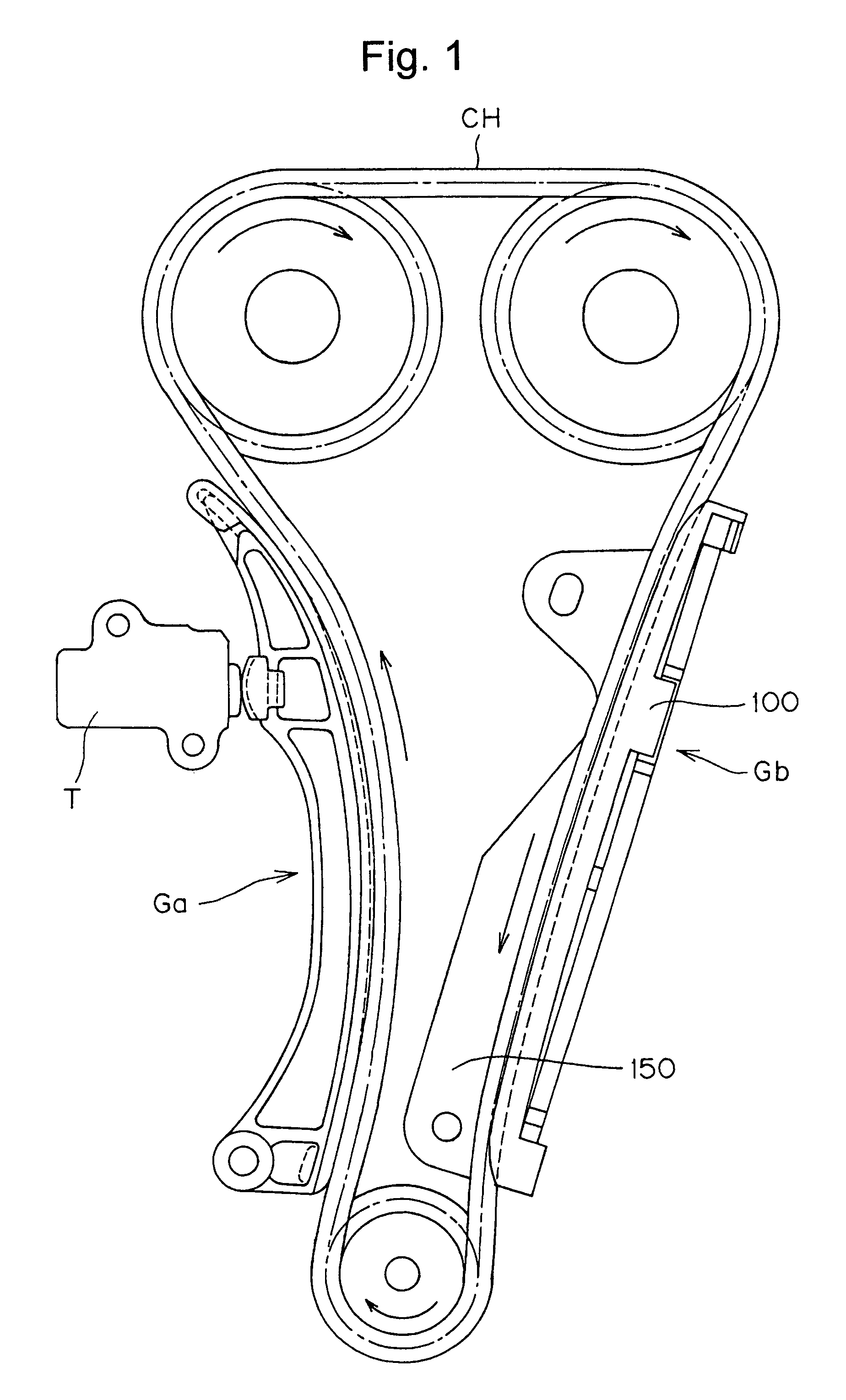
[0017]In the transmission shown in FIG. 1, a movable guide Ga and a fixed guide Gb, are provided respectively on the slack and tension sides of a drive chain CH arranged to be driven by a crankshaft sprocket and to drive two camshaft sprockets. The movable guide is pivoted, and urged by a tensioner T into sliding contact with the chain.

[0018]The movable guide Ga and the fixed guide Gb are similar, differing from each other primarily only in their shapes and in the methods by which they are attached to the engine block. The characterizing features of the invention reside in the structure of the backs of resin shoes of the guides, and will be described with reference to the fixed guide Gb. It should be understood, however, that the invention is applicable to movable guides as well as to fixed guides

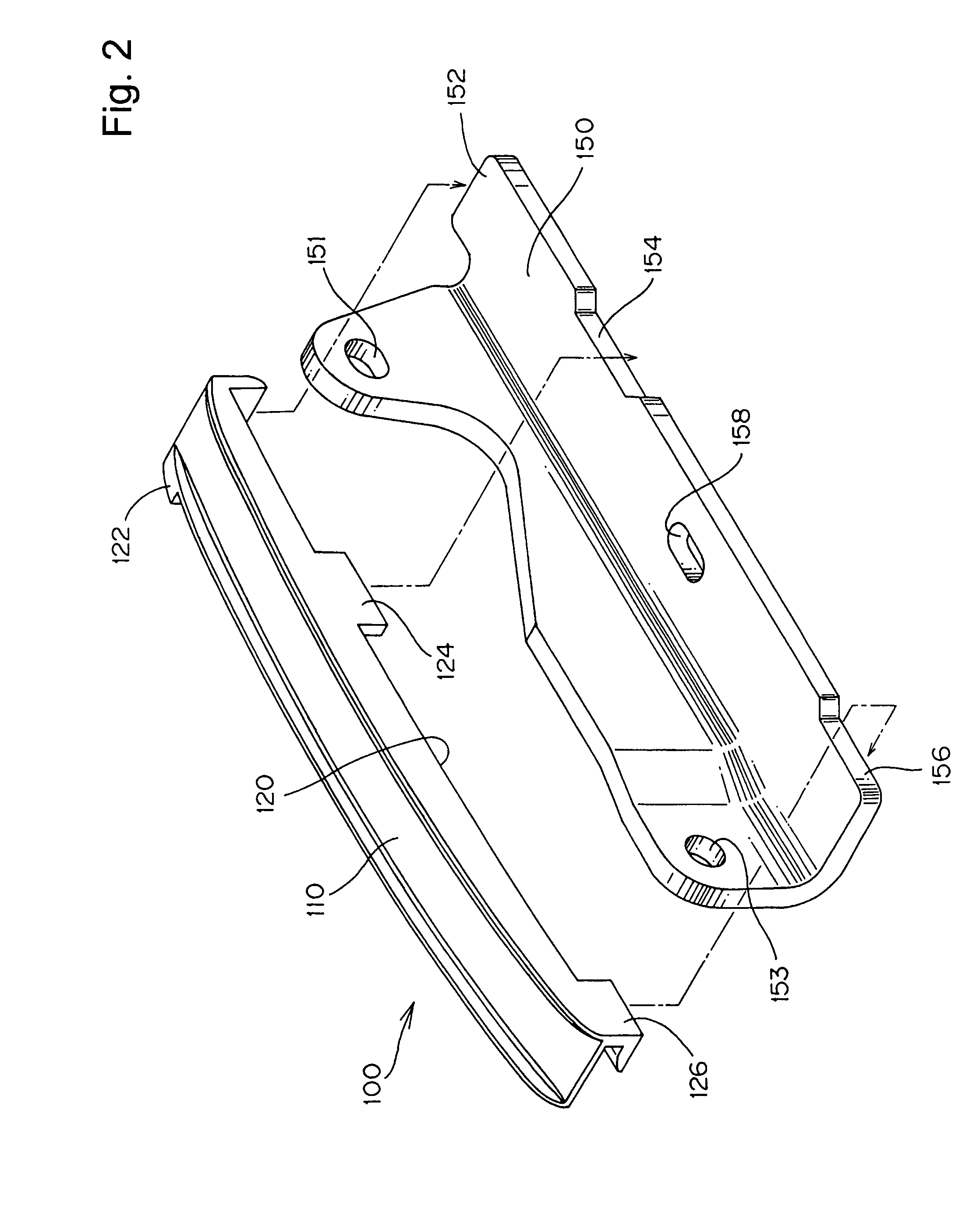
[0019]As shown in FIG. 2, a metal guide base 150 is provided with a flange having mounting holes 151 and 153 for receiving bolts by which the base can be secured to an engine block.

[0020]Re...


PUM


Abstract

In a sliding contact chain guide of the kind used in the timing transmission of an internal combustion engine, the back of the guide shoe, which engages a metal guide base, is formed with two, spaced longitudinal ribs, having between them a set of ribs formed in a lattice. The longitudinal ribs are wider than the ribs of the lattice.

Description

FIELD OF THE INVENTION[0001]This invention relates to a sliding contact guide for a flexible, traveling, transmission medium, used to transmit power from a driving shaft to one or more driven shafts in a transmission mechanism such as the timing drive of an internal combustion engine.BACKGROUND OF THE INVENTION[0002]An automobile engine generally includes a transmission device, which utilizes an endless, traveling, flexible, transmission medium, such as a roller chain, silent chain, toothed belt, or the like, to transmit rotation from the engine crankshaft to one or more valve-operating camshafts. In such a transmission device, sliding contact guides are used to guide the chain. Typically, a fixed guide is disposed in sliding engagement with the tension side of the chain, i.e., the side moving from a driven sprocket to the driving sprocket, and a movable guide is disposed in sliding engagement with the slack side of the chain, i.e., the side moving from the driving sprocket to a dri...

Claims


Application Information

Patent Timeline
Patent Type & Authority Patents(United States)
IPC IPC(8): F16H7/08F16H7/18
CPCF16H7/18
Inventor HIRAYAMA, MANABUSAITOH, TOYONAGAMORI, KAORIASAMI, FUMIO
Owner TSUBAKIMOTO CHAIN CO
Why Eureka
Try Eureka